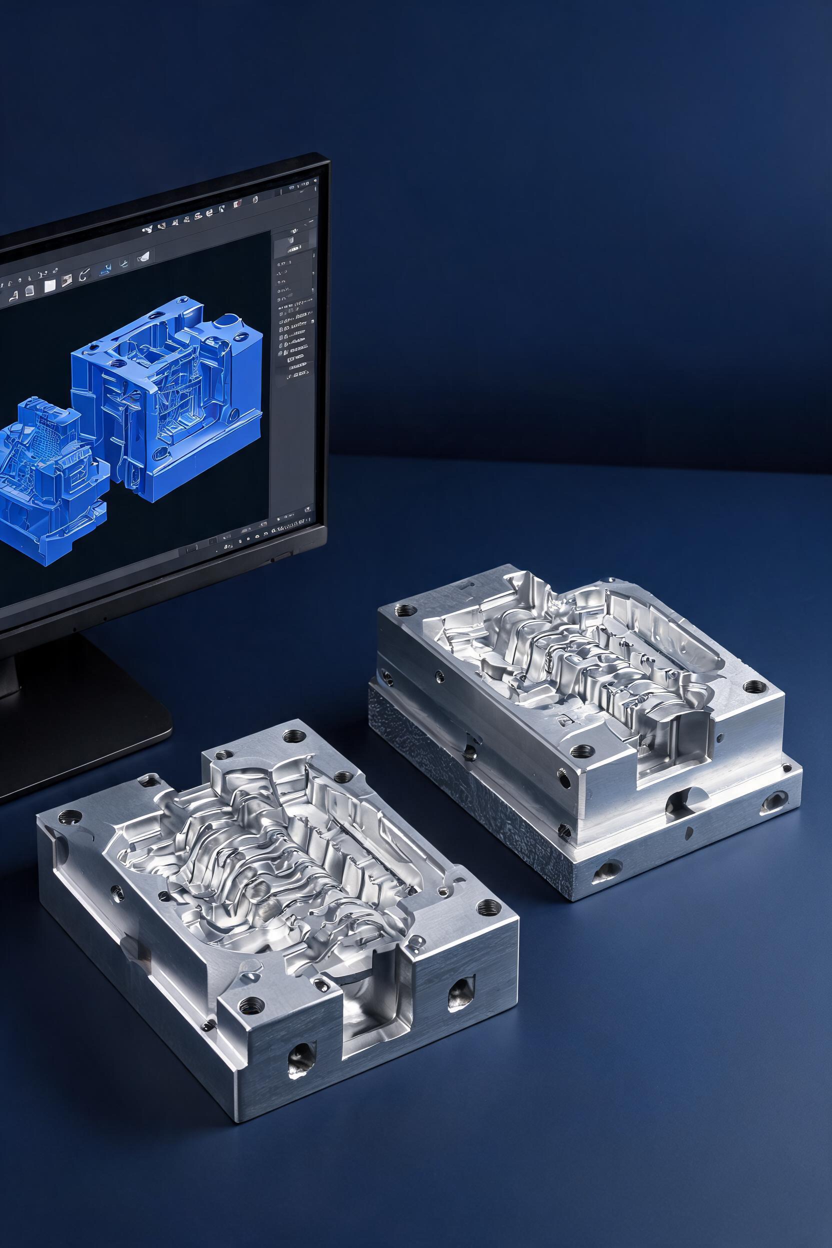
Liquid silicone rubber (LSR) is a high-performance thermoset elastomer with exceptional thermal stability (-60°C to 220°C), biocompatibility, low compression set, and chemical resistance, making it the material of choice for medical devices, automotive components, consumer electronics seals, and aerospace parts. Unlike thermoplastic injection molding, LSR processing relies on high-precision tooling to accommodate its low viscosity (1,000–10,000 cP before curing), exothermic crosslinking reaction, and strict dimensional tolerance requirements for critical applications. CNC precision silicone injection molding machining is the core process that translates part design intent into production-ready tooling, with the ability to achieve dimensional tolerances as tight as ±0.005 mm for micro-components and surface roughness down to Ra 0.05 μm for optical LSR parts. This guide provides a technical deep dive into the material-specific design considerations, machining workflows, quality control protocols, and troubleshooting methodologies for CNC-manufactured LSR injection molds, with actionable data for product engineers and tooling teams.
Design for CNC Machining of LSR Injection Molds
LSR’s unique curing and flow characteristics impose distinct constraints on mold design that differ significantly from thermoplastic tooling. Poor design choices can lead to flash, incomplete filling, dimensional deviation, and shortened mold lifespan, even with high-precision CNC machining. The following design principles are optimized for LSR processing and CNC machinability.
Material Selection for Mold Core and Cavity
The choice of mold steel directly impacts machining precision, wear resistance, and part quality, especially for high-volume production runs. LSR’s abrasive nature (filled grades often contain fumed silica or glass microspheres) and high curing temperatures require steels with high hardness, corrosion resistance, and thermal conductivity. Table 1 compares common mold materials for LSR applications:
Material GradeHardness (HRC)Thermal Conductivity (W/m·K)Corrosion ResistanceTypical ApplicationRecommended Production Volume
P2028–3229LowLow-volume prototyping<10,000 shots
420SS48–5224High (pre-hardened)Medical, food-grade parts10,000–100,000 shots
H1348–5424MediumHigh-volume industrial parts100,000–500,000 shots
S13650–5421ExcellentOptical LSR, high-purity medical parts>500,000 shots
Copper Alloy (C18000)95 HRB320MediumMicro-sized LSR parts requiring fast curingSpecialized high-precision runs
For applications requiring ultra-smooth surfaces (e.g., LSR contact lenses, light guides), S136 stainless steel is preferred, as it can be polished to Ra 0.05 μm without porosity. For molds intended for filled LSR grades, H13 or 420SS with PVD (Physical Vapor Deposition) coating (TiN or DLC, 2–5 μm thickness, 2500–3500 HV hardness) reduces abrasive wear by 60–70% compared to uncoated steels.
Critical Geometric Design Constraints for LSR Molds
LSR’s low viscosity allows it to flow into micro-cavities with feature sizes as small as 5 μm, but this same property makes it prone to flash even at parting line gaps of 0.002 mm. CNC machining processes must accommodate these constraints through intentional design choices:
- Parting line design: For micro LSR parts (weight <0.1 g), zero-gap interlocking parting lines with a 3° taper and 0.1 mm interference fit are required to prevent flash. CNC milling can achieve parting line flatness within 0.001 mm per 100 mm² surface area when using high-speed spindles (>20,000 RPM) and cubic boron nitride (CBN) cutting tools.
- Draft angles: Unlike thermoplastics, LSR parts shrink *during* curing (2.5–4% volumetric shrinkage, depending on formulation) and adhere to mold surfaces. Draft angles of 1–3° are recommended for vertical walls, increasing to 3–5° for wall heights >10 mm. For parts requiring zero draft (e.g., straight-walled medical catheters), polished S136 steel with a PTFE-based mold release coating reduces ejection force by 40–50%.
- Gating and runner systems: LSR is injected through cold runners (kept at 15–25°C to prevent premature curing) into heated cavities (150–200°C). CNC-machined cold runners should have a circular cross-section (diameter 3–8 mm) with a surface roughness <Ra 0.8 μm to minimize flow resistance. For multi-cavity molds, balanced hot runner systems with valve gates are preferred to ensure consistent fill across all cavities, with gate diameters sized to 0.2–1.0 mm depending on part wall thickness.
- Venting: During curing, LSR releases trace amounts of volatile organic compounds (VOCs) and trapped air that can cause voids or incomplete filling. CNC-machined vent slots 0.003–0.005 mm deep and 5–10 mm wide at the parting line allow air to escape without producing flash, while 0.5 mm deep vent overflow channels capture excess material. For micro-cavity molds, laser-drilled vent holes (10–20 μm diameter) are added to hard-to-reach cavity regions.
CNC Machining Workflow for LSR Injection Molds
The CNC machining process for LSR molds requires tighter process control than thermoplastic tooling, as even minor dimensional deviations can lead to defective parts. The workflow is divided into pre-machining preparation, precision milling and finishing, and post-machining surface treatment, each with LSR-specific optimizations.
Pre-Machining Preparation and CNC Programming
The pre-machining phase lays the foundation for dimensional accuracy by aligning tool path design with LSR mold requirements:
- 3D model validation and compensation: CAD models are adjusted to account for LSR’s curing shrinkage, with a shrinkage factor of 2.8–3.2% applied to all cavity dimensions for unfilled LSR, and 1.5–2.5% for filled grades (20–30% silica filler). For parts with tight tolerance features (<±0.01 mm), mold flow simulation software (e.g., Simcenter 3D, Moldex3D) is used to predict shrinkage variation across the part, with localized compensation factors applied to high-shrink regions (e.g., thick-walled sections).
- Cutting tool selection: High-speed steel (HSS) tools are only suitable for roughing soft P20 steel. For finishing hardened steels (HRC >48), solid carbide end mills with TiAlN coating are used, with cutting edge radii <0.001 mm for micro-feature machining. For ultra-precision polishing of optical LSR molds, single-crystal diamond tools achieve surface roughness down to Ra 0.02 μm. Table 2 outlines recommended cutting parameters for different machining stages:
Machining StageTool TypeSpindle Speed (RPM)Feed Rate (mm/min)Depth of Cut (mm)Tolerance Achievement
RoughingTiAlN-coated carbide end mill8,000–12,0001,500–2,5000.5–1.0±0.05 mm
Semi-finishingFine-grain carbide end mill15,000–20,000800–1,5000.1–0.3±0.01 mm
FinishingCBN or single-crystal diamond tool25,000–40,000300–8000.02–0.05±0.005 mm
- Workpiece fixturing: Vacuum chucks are used for thin mold inserts (<10 mm thickness) to prevent clamping deformation, while zero-point fixturing systems with repeatability <±0.002 mm ensure consistent positioning across multiple machining operations. For multi-cavity molds, a reference datum hole with tolerance ±0.001 mm is machined first to align all subsequent tool paths.
Precision Machining and In-Process Quality Checks
The machining phase combines high-speed milling, electrical discharge machining (EDM), and grinding to achieve the required precision for LSR molds:
- High-speed milling (HSM): HSM with dynamic tool path optimization reduces cutting forces by 30–40% compared to conventional milling, minimizing tool deflection and residual stress in the mold steel. For micro-cavity molds with feature sizes <0.1 mm, 5-axis CNC milling machines with positional accuracy <±0.003 mm per axis are used to machine complex undercuts and curved surfaces without re-fixturing.
- Sinker EDM for complex features: For features that cannot be milled (e.g., sharp internal corners, micro-textured surfaces), sinker EDM with graphite or copper electrodes is used. EDM achieves dimensional accuracy of ±0.002 mm and surface roughness down to Ra 0.2 μm, though the recast layer (1–5 μm thick) left on the mold surface must be removed via polishing to prevent LSR part adhesion. For medical LSR molds, the recast layer is limited to <0.5 μm to avoid leaching of metal particles into the part.
- In-process inspection: After each machining stage, a coordinate measuring machine (CMM) with 0.001 mm resolution is used to inspect 100% of critical dimensions, including cavity depth, parting line flatness, and gate diameter. For high-precision molds, laser scanning microscopy is used to verify surface roughness and micro-feature dimensions, with deviations >0.003 mm flagged for rework before proceeding to the next stage.
Post-Machining Treatment and Assembly
Post-machining processes ensure the mold can withstand LSR processing conditions and produce consistent part quality over its lifespan:
- Polishing and surface treatment: Mechanical polishing with diamond abrasives is used to achieve the required surface roughness, with Ra 0.8 μm standard for general-purpose parts, Ra 0.2 μm for medical parts, and Ra <0.05 μm for optical LSR parts. After polishing, molds intended for high-volume production are coated with a 2–3 μm thick DLC (Diamond-Like Carbon) coating, which reduces friction by 80% and extends mold lifespan by 2–3x compared to uncoated steel.
- Thermal stability testing: LSR molds operate at 150–200°C during production, so thermal expansion testing is performed to validate dimensional stability. The mold is heated to operating temperature for 4 hours, then critical dimensions are re-measured via CMM to ensure thermal expansion does not exceed 0.002 mm per 100 mm length. For molds with micro-features, thermal expansion is compensated for during the design phase by adjusting cavity dimensions to account for steel expansion at operating temperature.
- Mold assembly and dry run testing: Mold plates, core/cavity inserts, ejection pins, and heating elements are assembled with alignment tolerances <±0.003 mm. A dry run test with no material injected is performed to verify parting line closure, ejection system functionality, and temperature uniformity across the cavity (target ±1°C variation across all cavity regions). Temperature variation >2°C leads to uneven curing, resulting in dimensional deviation and variable part hardness.
Quality Control and Performance Validation for CNC-Machined LSR Molds
Even with precision machining, LSR molds require rigorous testing to ensure they meet production and part quality requirements. Quality control is divided into first-shot validation, long-term performance testing, and preventive maintenance protocols.
First-Shot Part Validation
The first batch of LSR parts produced from the mold is tested against design specifications to identify tooling defects:
- Dimensional inspection: 30 parts from the first production run are measured via CMM to verify compliance with tolerance requirements. For critical features, the process capability index (Cpk) is calculated, with a minimum Cpk of 1.33 required for stable production. If Cpk is <1.33, dimensional adjustments are made to the mold via CNC re-machining to center the process within tolerance limits.
- Material property validation: Cured LSR parts are tested for hardness (Shore A durometer, ±2 tolerance), tensile strength (±5% tolerance per ISO 37), and compression set (<20% after 22 hours at 175°C per ASTM D395). Deviations in material properties often indicate uneven cavity temperature or incomplete filling, which can be resolved by adjusting heating element placement or optimizing venting.
- Flash and defect assessment: Parts are inspected under 100x magnification for flash, voids, and knit lines. Flash <0.01 mm is acceptable for most industrial applications, while medical and optical parts require zero flash. If flash is present, the parting line is re-machined to improve flatness, or vent depth is reduced to limit material escape.
Long-Term Mold Performance Testing
For high-volume production molds, accelerated lifecycle testing is performed to validate durability:
- Abrasion resistance testing: The mold is run for 10,000 cycles with filled LSR, then cavity surface roughness and dimensional tolerance are re-measured. For coated molds, surface roughness increase should be <0.05 μm, and dimensional deviation <0.005 mm after 10,000 cycles. Uncoated molds typically show 2–3x higher wear rates, requiring more frequent maintenance.
- Corrosion resistance testing: Molds intended for medical LSR grades (which often contain platinum curing agents) are exposed to 100 hours of 85°C/85% relative humidity testing, with no visible corrosion allowed on cavity surfaces. 420SS and S136 steels pass this test without coating, while P20 molds require a nickel plating to prevent corrosion.
- Maintenance interval validation: The optimal preventive maintenance schedule is determined based on wear testing. For uncoated molds running filled LSR, maintenance (polishing and wear inspection) is required every 50,000 shots, while DLC-coated molds can run 150,000–200,000 shots between maintenance cycles.
Troubleshooting Common CNC Machining Defects in LSR Molds
Even with strict process control, LSR molds can develop defects during machining or production that impact part quality. Table 3 outlines common defects, root causes, and corrective actions:
DefectRoot CauseCorrective Action
Persistent flash at parting lineParting line flatness deviation >0.002 mm, or insufficient clamping forceRe-machine parting line via high-speed milling to achieve flatness <0.001 mm per 100 mm²; verify clamping force is 5–7 tons per 100 cm² of projected part area
LSR part adhesion to cavityHigh cavity surface roughness (>Ra 0.8 μm) or residual EDM recast layerPolish cavity to Ra <0.4 μm; apply DLC or PTFE coating; increase draft angle by 1–2°
Dimensional deviation >0.01 mmUnaccounted LSR shrinkage, or thermal expansion of mold during operationAdjust cavity dimensions via re-machining to compensate for measured shrinkage; optimize heating system to reduce cavity temperature variation to <±1°C
Micro-voids in LSR partsInsufficient venting or trapped air in cavityAdd 0.004 mm deep vent slots at the last fill point of the cavity; increase injection hold time by 2–3 seconds
Uneven curing across partNon-uniform cavity temperature, or unbalanced runner systemAdjust heating element placement to eliminate hot/cold spots; re-machine runners to ensure balanced fill across all cavities
Conclusion
CNC precision silicone injection molding machining is a highly specialized process that requires close alignment between LSR material properties, mold design, machining parameters, and quality control protocols. For critical applications such as medical implants and optical LSR parts, the combination of 5-axis high-speed milling, precision EDM, and in-process CMM inspection can achieve dimensional tolerances as tight as ±0.005 mm and surface roughness down to Ra 0.05 μm, with mold lifespans exceeding 500,000 shots when using coated high-grade steel. Key success factors include applying LSR-specific shrinkage compensation during design, selecting appropriate mold materials and coatings for the application, and validating both mold dimensional stability and part performance before full-scale production. As demand for high-precision LSR components continues to grow in electric vehicle, wearable medical device, and consumer electronics markets, advancements in CNC machining technology (including AI-optimized tool paths and in-situ metrology) will further reduce tolerance limits and production costs for LSR injection molds. For engineering teams, following the design and machining best practices outlined in this guide will minimize tooling rework, reduce production lead times, and ensure consistent part quality across the entire mold lifespan.