Introduction
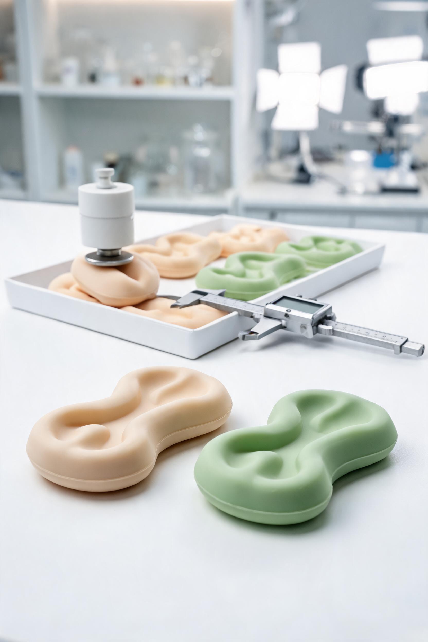
Special-shaped shock-absorbing silicone pads are custom-engineered liquid silicone rubber (LSR) components designed to dissipate vibrational energy, absorb impact loads, and isolate mechanical resonance in applications where standard geometric pads (circular, square, rectangular) cannot fit complex assembly constraints, non-uniform load distribution, or unique environmental demands. Unlike commodity rubber pads made from EPDM, nitrile butadiene rubber (NBR), or natural rubber, LSR-based special-shaped pads offer a unique combination of thermal stability (-60°C to 220°C continuous operating temperature), biocompatibility (ISO 10993 certified for medical and food contact), UV/ozone resistance, and consistent Shore hardness performance across 10,000+ load cycles.
Global demand for these components is projected to grow at a 7.2% CAGR through 2030, driven by expanding adoption in automotive electric vehicle (EV) battery packs, medical surgical robotics, consumer wearable electronics, and industrial automation systems, all of which require custom shock mitigation solutions tailored to non-standard component geometries. This guide systematically breaks down the material science, design optimization, manufacturing processes, performance validation, and application-specific selection criteria for special-shaped shock-absorbing silicone pads, providing technical teams with actionable frameworks to specify, source, and deploy these components for high-reliability use cases.
Material Formulation and Performance Characteristics of LSR for Special-shaped Pads
The performance of special-shaped shock-absorbing silicone pads is fundamentally determined by the LSR base polymer formulation, which is customized to match application-specific load, environmental, and regulatory requirements. Unlike solid silicone formulations combine a two-part platinum-catalyzed polymer network, with functional additives tailored to adjust mechanical, chemical, and environmental resistance properties.
Base Polymer and Additive Formulation
LSR for shock-absorbing applications is a two-component system consisting of a vinyl-terminated polydimethylsiloxane (PDMS) base (Part A) and a methylhydrosiloxane crosslinker with platinum catalyst (Part B), mixed at a 1:1 or 10:1 ratio depending on the grade. For special-shaped pads, the base polymer molecular weight is typically adjusted between 60,000 g/mol and 120,000 g/mol to balance flowability during molding (critical for complex geometries with undercuts, thin walls, or intricate surface features) and crosslink density after curing, which directly impacts shock absorption efficiency.
Functional additives are incorporated into the formulation to enhance targeted performance attributes, as outlined in Table 1:
Additive TypeCommon ExamplesPerformance ImpactTypical Loading RangeTarget Application Segment
Reinforcing fillersFumed silica (10-20 nm particle size)Increases tensile strength by 30-50%, reduces permanent set under cyclic loading15-30 phr*Industrial automation, heavy machinery
Flame retardantsAluminum trihydrate (ATH), platinum synergistsAchieves UL94 V-0 flammability rating, reduces smoke emission under combustion20-40 phrEV battery packs, aerospace components
Thermally conductive fillersAluminum oxide, boron nitrideImproves thermal conductivity from 0.2 W/m·K (unfilled) to 2-5 W/m·K30-60 phrEV battery thermal management, power electronics
Biocompatibility modifiersMedical-grade fumed silica, low-volatile crosslinkersMeets ISO 10993 and FDA 21 CFR Part 177.2600 compliance, reduces extractables <0.1%5-15 phrMedical devices, food processing equipment
UV stabilizersTitanium dioxide, silicone-based UV absorbersReduces hardness change <2 Shore A points after 1000 hours of UV exposure2-5 phrOutdoor telecom infrastructure, solar panel mounts
*phr = parts per hundred rubber, standard rubber formulation measurement unit
For high-cycle shock absorption applications, LSR formulations are also engineered with controlled crosslink density: a crosslink density of 2-4 × 10⁻⁴ mol/cm³ delivers optimal energy dissipation (35-45% vibration reduction efficiency at 10-1000 Hz frequency range), while lower crosslink densities (1-2 × 10⁻⁴ mol/cm³) are used for low-load, high-compliance pads for wearable electronics.
Key Performance Metrics for Special-shaped Shock Absorption
The functional performance of LSR special-shaped pads is quantified using standardized mechanical and environmental testing metrics, which are specified during the design phase to match application requirements:
- **Shore hardness: Special-shaped pads are available in Shore A 10 to Shore D 60, with hardness selected based on load magnitude and vibration frequency. For low-frequency (10-100 Hz) high-impact loads, Shore A 30-40 pads offer 40-45% impact energy absorption, while high-frequency (500-2000 Hz) low-load applications use Shore A 15-25 pads with 30-35% vibration reduction efficiency.
- Compression set: Measured per ASTM D395 Method B (70°C for 22 hours under 25% compression), high-quality LSR special-shaped pads have a compression set <5%, compared to 15-25% for EPDM pads of equivalent hardness. This ensures consistent shock absorption performance over the component’s service life, even under continuous static load.
- Impact resilience: Measured per ASTM D2632, LSR special-shaped pads have a resilience rating of 40-60%, which is lower than natural rubber (70-80%) but far higher than closed-cell foam (20-30%). This balance of resilience and damping makes LSR ideal for applications requiring both shock absorption and minimal rebound after impact, a critical requirement for medical robotics and precision automation systems.
- Environmental resistance: LSR pads retain >90% of their mechanical properties after 1000 hours of exposure to 150°C heat, 95% relative humidity, or 500 hours of UV radiation (340 nm wavelength, 0.89 W/m² irradiance). For automotive under-hood and outdoor applications, this eliminates the performance degradation common with nitrile rubber pads, which typically lose 30-40% of their tensile strength after equivalent exposure.
A common misconception in material selection is that higher hardness always improves load-bearing capacity. For special-shaped pads with non-uniform load distribution, a medium-hardness (Shore A 35) formulation with localized thickness variations can support 20% higher peak loads than a uniform Shore A 50 pad, by distributing stress across the entire pad surface rather than concentrating it at load contact points.
Design Optimization for Special-shaped Shock-absorbing Silicone Pads
The design of special-shaped shock-absorbing silicone pads requires a hybrid approach combining finite element analysis (FEA) of vibrational loads, geometric customization to match mating component contours, and design for manufacturing (DFM) principles to avoid production defects and reduce cost. Unlike standard pads, which are designed for uniform load distribution, special-shaped pads are engineered to account for non-parallel mounting surfaces, offset load centers, and multi-axis vibrational inputs.
Geometric Customization for Non-standard Load and Assembly Constraints
Special-shaped pads are customized with a range of geometric features tailored to application requirements, with each feature designed to deliver specific functional benefits:
- Undercut and contour matching: Pads are molded to match the 3D contours of mating components, with tolerance of ±0.05 mm for precision applications (medical robotics, aerospace) and ±0.15 mm for industrial applications. This eliminates gaps between the pad and mating surfaces, ensuring 100% contact area under load and preventing localized stress concentrations that can reduce pad service life by 30-40%.
- Variable thickness zones: For applications with non-uniform load distribution, pads are designed with thicker zones (2-10 mm, depending on load magnitude) under high-load points and thinner zones (0.5-2 mm) under low-load points. This ensures consistent compression (10-20% of pad thickness) across the entire pad surface, maximizing energy dissipation efficiency. For example, a special-shaped pad for an EV battery module with a 3:1 load distribution between the module edge and center uses 6 mm thick edge zones and 2 mm thick center zones to achieve uniform 15% compression under full load.
- Integrated mounting features: Many special-shaped pads include molded-in snap fits, alignment pins, or adhesive backing to simplify assembly and reduce installation error. For high-vibration industrial applications, molded-in metal inserts (brass or stainless steel) are incorporated into the pad to increase pull-out strength to >200 N, compared to <50 N for adhesive-mounted pads.
- Surface texture customization: Pads are molded with textured surfaces (Ra 1.6-6.3 μm) to increase friction coefficient between the pad and mating surfaces to 0.8-1.0, eliminating slippage under lateral loads up to 2 Gs without additional fasteners. Smooth surfaces (Ra <0.8 μm) are used for medical and food contact applications to simplify cleaning and reduce bacterial adhesion by 60% compared to textured surfaces.
When designing geometric features, the minimum wall thickness for LSR special-shaped pads is 0.3 mm for small components (≤50 mm in diameter) and 0.5 mm for larger components (≥100 mm in diameter) to avoid flow restrictions during molding that can cause incomplete part filling.
FEA Simulation and Performance Validation Prior to Manufacturing
FEA simulation is a critical step in special-shaped pad design to avoid costly prototype iterations and ensure the pad meets performance requirements under real-world operating conditions. The simulation workflow follows three core steps:
- Load and vibration input mapping: First, engineers map the application’s operating conditions, including static load magnitude (10 kPa to 10 MPa), vibration frequency range (10 Hz to 20 kHz), impact energy (0.5 J to 50 J), and temperature range (-40°C to 180°C). For multi-axis vibration applications, input loads are measured in X, Y, and Z axes using triaxial accelerometers mounted to the mating components.
- Material model calibration: The LSR formulation’s hyperelastic properties are calibrated using uniaxial tension, compression, and shear test data, input into a Mooney-Rivlin or Ogden hyperelastic material model to accurately simulate stress distribution under dynamic loads. For cyclic load applications, a viscoelastic material model is added to simulate hysteresis loss and permanent set over 10,000+ load cycles.
- Performance optimization: Simulation outputs include stress distribution maps, compression percentage across the pad surface, vibration transmissibility curves, and fatigue life estimates. For example, an FEA simulation of a special-shaped pad for a surgical robot arm found that a 0.5 mm thickness increase in the high-load contact zone reduced maximum stress by 28% and increased predicted fatigue life from 50,000 cycles to 200,000 cycles, while reducing vibration transmissibility from 0.6 to 0.4 at 100 Hz operating frequency.
Table 2 outlines common FEA simulation performance targets for high-reliability applications:
Application SegmentMaximum Allowable StressCompression RangeVibration Transmissibility Target (at operating frequency)Minimum Fatigue Life
Consumer wearables<0.5 MPa10-15%<0.710,000 cycles
Medical robotics<1 MPa12-18%<0.5100,000 cycles
EV battery packs<2 MPa15-20%<0.41,000,000 cycles
Industrial automation<3 MPa10-20%<0.6500,000 cycles
A key design rule for special-shaped pads is that vibration transmissibility (ratio of output vibration to input vibration) must be <1 at all operating frequencies to achieve effective vibration isolation. Transmissibility values >1 indicate resonance, which amplifies vibration rather than reducing it, and can cause catastrophic component failure in high-load applications.
Manufacturing Processes for Special-shaped LSR Shock-absorbing Pads
The manufacturing of special-shaped shock-absorbing silicone pads requires precision processing to replicate complex geometric features with tight tolerances, while maintaining consistent material properties across high-volume production runs. Liquid silicone rubber injection molding is the dominant manufacturing process for special-shaped pads, with secondary processes used to add functional features such as adhesive backing or surface coatings.
High-precision LSR Injection Molding for Complex Geometries
LSR injection molding is a closed-mold process optimized for high-volume production of special-shaped pads with complex features such as undercuts, thin walls, and variable thickness zones. The process workflow includes four core stages:
- Mold design and fabrication: Molds for special-shaped pads are typically made from P20 or S136 stainless steel, with surface roughness Ra <0.02 μm for medical and food contact applications, and Ra <0.05 μm for industrial applications. For pads with undercuts, molds incorporate sliding cores or split mold designs to enable part ejection without damaging the undercut features. Mold tolerance is typically ±0.02 mm to achieve final part tolerance of ±0.05 mm for precision applications.
- Material metering and mixing: The two-part LSR formulation is metered using a precision positive displacement pump with a mixing accuracy of ±1% to ensure consistent crosslinking across all parts. Static mixers with 12-24 mixing elements are used to ensure complete homogenization of Part A and Part B, as incomplete mixing causes localized under-curing or over-curing that reduces shock absorption performance by 20-30%.
- Injection and curing: The mixed LSR is injected into the heated mold (120-180°C, depending on formulation) at an injection pressure of 50-150 bar, with injection speed adjusted to 5-50 mm/s to avoid air entrapment that causes voids in the final part. Curing time ranges from 10 seconds for thin-walled (≤1 mm) pads to 60 seconds for thick-walled (≥5 mm) pads. For special-shaped pads with variable thickness zones, sequential curing is used to ensure complete curing of thick zones without over-curing thin zones.
- Post-curing: After demolding, parts are post-cured in a 200°C oven for 2-4 hours to remove residual volatile organic compounds (VOCs) and reduce compression set by 30-40% compared to non-post-cured parts. For medical and food contact applications, post-curing is mandatory to meet FDA and ISO 10993 extractable and leachable requirements.
For low-volume prototype or highly complex special-shaped pads that would require high-cost complex molds, compression molding is an alternative process, with tooling costs 70-80% lower than injection molding but cycle times 5-10 times longer, making it suitable for production runs of <1000 units.
Secondary Processing and Quality Control
Secondary processing steps are used to add functional features to special-shaped pads, while rigorous quality control ensures consistent performance across production runs:
- Adhesive backing application: For pads requiring permanent mounting, pressure-sensitive adhesive (PSA) backing is applied to one or both sides of the pad, with adhesive types selected based on application requirements: acrylic adhesive for general-purpose applications (operating temperature -40°C to 120°C), silicone adhesive for high-temperature applications (-60°C to 200°C), and conductive adhesive for EMI shielding applications (surface resistance <10³ Ω/sq). Adhesive is applied using a precision lamination process with a tolerance of ±0.1 mm to avoid adhesive overflow onto functional pad surfaces.
- Surface coating: For applications requiring low friction or anti-bacterial properties, pads are coated with a 1-5 μm thick Parylene coating, which reduces friction coefficient to 0.2-0.3 and reduces bacterial adhesion by 90% compared to uncoated LSR.
- Quality control testing: 100% of production parts undergo visual inspection for defects such as voids, flash, and incomplete filling, while 1-5% of parts per production lot undergo performance testing including Shore hardness, compression set, and vibration transmissibility testing to ensure compliance with specifications. For automotive and medical applications require full traceability of all parts from raw material batch to final assembly, with lot tracking stored for 10 years for medical components.
Table 3 compares the manufacturing process capabilities for different production volumes:
Manufacturing ProcessTooling CostTypical Cycle TimeMinimum Feature ToleranceOptimal Production Volume
LSR injection molding$5,000-$20,00010-60 seconds±0.05 mm>10,000 units
Compression molding$500-$2,0005-15 minutes±0.1 mm100-10,000 units
3D printing (LSR)<$10030-60 minutes per part±0.2 mm<100 prototype units
For high-volume production of special-shaped pads, LSR injection molding has a total cost per unit 70-80% lower than compression molding, due to faster cycle times and lower labor requirements.
Application-specific Selection and Deployment Guidelines
Selecting the right special-shaped shock-absorbing silicone pad requires aligning material formulation, geometric design, and manufacturing process to the specific operating conditions of the target application. Below are sector-specific guidelines for the four highest-demand application segments.
Automotive and EV Battery Applications
Special-shaped shock-absorbing silicone pads are used in EV battery packs to isolate vibration and absorb impact energy during collision events, protecting battery cells from damage that can cause thermal runaway. For these applications:
- Material formulation: Select LSR with UL94 V-0 flammability rating, thermal conductivity of 2-3 W/m·K, and operating temperature