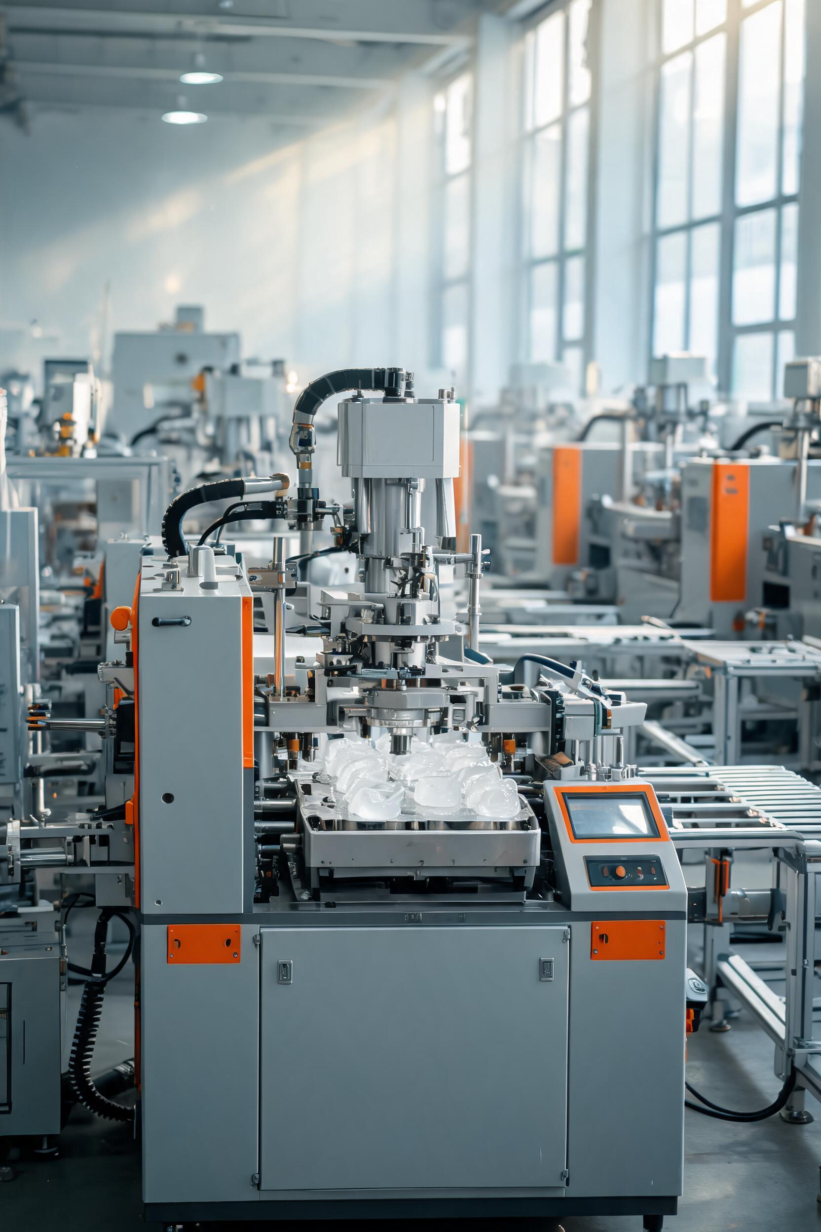
Plastic insert injection molding, a hybrid manufacturing process that integrates pre-formed insert components into a thermoplastic or thermoset matrix during the molding cycle, has emerged as a critical solution for industries requiring parts with combined material properties, complex geometries, and high structural integrity. Unlike conventional injection molding that produces homogeneous plastic parts, this process enables engineers to combine the rigidity, conductivity, or wear resistance of metal, ceramic, or composite inserts with the low cost, design flexibility, and weight reduction of molded plastics. Global demand for insert-molded components is projected to grow at a 6.2% CAGR through 2030, driven by rising adoption in automotive electrification, consumer electronics miniaturization, and medical device miniaturization. However, the process introduces unique technical challenges related to insert alignment, material compatibility, and cycle time optimization that distinguish it from standard injection molding workflows. This analysis provides a systematic breakdown of the plastic insert injection molding process, from material selection frameworks to quality control methodologies, and outlines actionable strategies to mitigate common production defects.
Core Material Selection Principles for Insert Molding
The performance of insert-molded parts is fundamentally dependent on the compatibility between the insert material and the overmolded polymer, as well as the alignment of material properties with end-use operating conditions. Unlike single-material molding, insert molding requires engineers to evaluate both intrinsic material characteristics and inter-material interaction effects to avoid premature part failure.
Insert Material Classification and Property Matching
Inserts are selected based on the functional requirement they are designed to fulfill, with common categories including structural, conductive, and wear-resistant inserts. Table 1 summarizes the most widely used insert materials, their key properties, and typical application scenarios:
Insert MaterialTensile Strength (MPa)Coefficient of Thermal Expansion (CTE, ppm/°C)Primary FunctionCommon Applications
Cold-rolled steel350–50011–13Structural load bearing, thread reinforcementAutomotive bracket mounts, power tool housings
6061 Aluminum270–31023–24Lightweight structural support, heat dissipationConsumer electronics chassis, LED heat sinks
Brass C3600300–36019–20Electrical conductivity, corrosion resistanceConnector pins, medical device electrical terminals
304 Stainless Steel505–70017–19Corrosion resistance, high-temperature stabilityFood processing equipment components, surgical instrument parts
Zirconia Ceramic800–100010–11Wear resistance, electrical insulationHigh-precision bearing components, semiconductor manufacturing fixtures
A critical parameter in material pairing is the CTE mismatch between the insert and the overmolded polymer. A CTE difference exceeding 15 ppm/°C typically leads to residual thermal stress during the cooling phase, which can cause interface delamination, polymer cracking, or insert loosening under cyclic temperature loads. For high-temperature operating environments (e.g., automotive under-hood components with operating ranges from -40°C to 150°C), engineers often use glass-filled thermoplastics to reduce polymer CTE: for example, 30% glass-filled polyamide 6 (PA6) has a CTE of 15–20 ppm/°C, which closely matches aluminum’s 23–24 ppm/°C, reducing residual stress by up to 72% compared to unfilled PA6.
Polymer Matrix Selection Criteria
The overmolded polymer must balance processability, adhesion to the insert, and end-use performance. Key selection criteria include:
- Melt flow index (MFI): Polymers with MFI ≥ 10 g/10min (tested at 230°C/2.16kg for polyolefins, 270°C/2.16kg for engineering thermoplastics) are preferred for insert molding, as their low viscosity enables complete cavity filling without applying excessive pressure that could displace inserts.
- Adhesion promoters: For low-surface-energy polymers such as polypropylene (PP) or polyethylene (PE), maleic anhydride-grafted grades can improve interfacial bond strength with metal inserts by up to 450% compared to unmodified grades, by forming chemical bonds with oxide layers on the metal surface.
- Shrinkage rate: Semi-crystalline polymers such as PA6 and polybutylene terephthalate (PBT) have higher shrinkage (1.2–2.0%) than amorphous polymers such as acrylonitrile butadiene styrene (ABS) and polycarbonate (PC) (0.4–0.8%). While higher shrinkage can create a stronger mechanical grip around rigid inserts, it also increases the risk of insert bending if the insert has low flexural modulus (e.g., thin aluminum inserts < 1mm thick).
For medical insert-molded components, additional criteria include biocompatibility (ISO 10993 certification), sterilization resistance (autoclave, gamma radiation, or ethylene oxide compatibility), and low leachables, which often narrow material choices to medical-grade PC, cyclic olefin copolymer (COC), or liquid silicone rubber (LSR) overmolded on 316L stainless steel inserts.
Process Flow and Key Parameter Optimization
Plastic insert molding extends the standard injection molding cycle with insert loading and post-molding handling steps, each of which introduces variables that impact part quality and production efficiency. A typical cycle ranges from 30 seconds for small consumer electronic components to 180 seconds for large automotive structural parts, with insert handling contributing 20–40% of total cycle time.
Step-by-Step Process Workflow
The insert molding process follows a standardized sequence to ensure repeatability:
- Insert preparation: Inserts are cleaned via ultrasonic washing, plasma treatment, or chemical etching to remove surface contaminants (e.g., machining oils, oxide layers) and increase surface roughness, which improves mechanical interlocking with the polymer. For metal inserts, a surface roughness (Ra) of 1.5–3.0 μm is optimal: rougher surfaces increase bond strength by 30–60% compared to polished surfaces, while surfaces with Ra > 4.0 μm can trap air bubbles at the interface that reduce adhesion.
- Insert loading: Inserts are placed into mold cavities either manually (for low-volume production, < 1,000 parts/year) or via robotic end-of-arm tooling (EOAT) for high-volume runs. Precision loading is critical: positional tolerance for inserts is typically ±0.02 mm for electronic connector applications, as even 0.05 mm of misalignment can lead to mating failures in final assembly. For multi-cavity molds, vision inspection systems integrated into the EOAT verify insert alignment before the mold closes, reducing scrap rates from misaligned inserts by up to 98%.
- Mold closing and clamping: The mold is closed with clamping force calculated based on the projected area of the part and insert. The required clamping force is 2–3 tons per square inch of projected area, 10–15% higher than standard injection molding to account for the reduced compressibility of inserts, which prevents flash formation at the insert-polymer interface.
- Injection and holding: Molten polymer is injected into the cavity at a controlled rate, with injection pressure typically ranging from 80–120 MPa. A holding pressure of 50–70% of injection pressure is applied for 30–60% of the cooling cycle to compensate for polymer shrinkage and ensure full contact between the polymer and insert surface. For parts with complex insert geometries, sequential valve gating is used to control melt flow direction, reducing shear stress on fragile inserts and minimizing weld line formation near insert surfaces.
- Cooling and ejection: The mold is cooled to a temperature 10–20°C below the polymer’s glass transition temperature (for amorphous polymers) or heat deflection temperature (for semi-crystalline polymers). Inserts with high thermal conductivity (e.g., copper or aluminum) act as internal heat sinks, reducing cooling time by 15–25% compared to equivalent all-plastic parts. Ejector pins are positioned to apply force evenly across the part, avoiding contact with inserts that could cause bending or dislodgement.
- Post-processing: Finished parts undergo deflashing, insert thread tapping (if required), and functional testing. For high-precision applications, annealing at 80–120°C for 2–4 hours is performed to relieve residual thermal stress, improving interface bond strength by 15–25% and reducing long-term dimensional drift.
Critical Process Parameter Tuning
Even minor deviations in process parameters can lead to defects in insert-molded parts, making systematic tuning essential for consistent production. Table 2 outlines the impact of key parameters on common defects and recommended tuning ranges for PA6 overmolded on aluminum inserts:
ParameterRecommended RangeImpact of UndersettingImpact of Oversetting
Melt Temperature260–280°CPoor polymer flow, incomplete interface wetting, low bond strengthPolymer degradation, flash formation, insert thermal expansion mismatch stress
Mold Temperature80–100°CPremature polymer solidification, reduced interdiffusion at interface, high residual stressExtended cycle time, increased part shrinkage, insert misalignment due to softening of mold locating pins
Injection Speed50–80 mm/sLong fill time, cold weld lines, uneven pressure distribution around insertHigh shear stress, insert displacement, air entrapment at insert-polymer interface
Holding Pressure40–60 MPaInsufficient shrinkage compensation, voids near insert, low mechanical gripInsert bending, mold core deflection, high part ejection force
Cooling Time20–30 sIncomplete polymer solidification, insert loosening during ejection, dimensional warpageReduced production output, increased energy consumption
For insert molding with heat-sensitive inserts (e.g., glass or ceramic inserts prone to thermal shock), a gradual pre-heating step for inserts to 60–80% of the mold temperature is recommended, reducing the temperature gradient during injection and lowering the risk of insert cracking by up to 85%.
Common Defect Root Cause Analysis and Mitigation Strategies
Insert molding has a higher inherent defect risk than standard injection molding, with typical scrap rates ranging from 2–8% for well-optimized processes, compared to 1–3% for homogeneous plastic parts. Most defects stem from interface compatibility issues, insert positioning errors, or process parameter inconsistencies, all of which can be mitigated with systematic troubleshooting.
Insert-Related Defects
The most common insert-related defects are misalignment, loosening, and corrosion:
- Insert misalignment: Occurs when inserts shift during mold closing or polymer injection, leading to parts that fail dimensional or functional specifications. Root causes include insufficient insert retention force in the mold, unbalanced melt flow, or excessive injection speed. Mitigation strategies include:
- Adding spring-loaded locating pins or magnetic inserts in the mold cavity to hold inserts in place, increasing retention force by 3–5 times compared to friction-only fits
- Optimizing gating locations to direct melt flow parallel to insert long axes, reducing lateral shear force on inserts by up to 60%
- Using pressure sensors in the mold cavity to monitor real-time pressure distribution around inserts, triggering an automatic stop if pressure imbalance exceeds 10%
- Insert loosening: Defined as a pull-out force of less than 70% of the design specification, usually caused by poor interfacial adhesion or insufficient shrinkage grip. Mitigation steps include:
- Adding undercuts, knurls, or circumferential grooves on insert surfaces to create mechanical interlocking, which can increase pull-out force by 200–400% compared to smooth inserts
- Applying adhesive coatings (e.g., epoxy-based primers) to insert surfaces before molding, creating a chemical bond between the insert and polymer for high-vibration applications
- Adjusting cooling rates to ensure polymer shrinkage occurs evenly around the insert, avoiding uneven stress distribution that can create gaps at the interface
- Insert corrosion: A common failure mode for metal inserts in outdoor or high-humidity applications, caused by moisture penetration at the insert-polymer interface. Mitigation includes using coated inserts (e.g., zinc-plated steel, anodized aluminum) and selecting polymers with low moisture absorption (e.g., PBT, polyphenylene sulfide (PPS)) instead of hygroscopic materials such as PA6.
Polymer and Interface Defects
Polymer-related defects in insert molding include delamination, cracking, and void formation:
- Interface delamination: The separation of the polymer matrix from the insert surface, usually caused by surface contamination, low mold temperature, or excessive CTE mismatch. Mitigation strategies include:
- Implementing in-line plasma treatment of inserts immediately before loading, increasing surface energy to ≥ 72 mN/m to ensure full wetting by molten polymer
- Using polymer grades with tailored CTE to match insert material, reducing residual thermal stress at the interface
- Performing interface bond strength testing via lap shear tests for every production batch, with a minimum acceptable shear strength of 15 MPa for structural applications
- Polymer cracking near inserts: Caused by high residual stress from rapid cooling or excessive holding pressure. Cracks typically initiate at sharp corners on inserts, so designing inserts with a minimum corner radius of 0.5 mm reduces stress concentration by up to 40%. Annealing post-molding is also effective for stress relief, reducing crack formation under cyclic temperature loads by 70–80%.
- Voids near insert surfaces: Formed by air entrapment during injection or insufficient holding pressure. Voids reduce both interface bond strength and structural integrity, so mitigation includes adding venting channels (0.02–0.03 mm deep) near insert locations to evacuate trapped air, and using gas-assisted injection molding for thick-walled parts to reduce void formation by up to 90%.
Quality Control and Production Scaling Best Practices
Consistent quality in insert molding requires a combination of in-process monitoring, standardized testing protocols, and design for manufacturing (DFM) optimization, especially when scaling from prototype to high-volume production.
In-Process Monitoring and Testing Methodologies
Advanced monitoring technologies have reduced scrap rates in high-volume insert molding operations by up to 60% by enabling real-time defect detection:
- Vision inspection systems: High-resolution cameras capture images of insert position after loading and after part ejection, verifying alignment within ±0.01 mm and detecting missing or damaged inserts. For multi-cavity molds running 10,000+ parts per day, vision systems operate at 30 frames per second with 99.98% detection accuracy.
- Cavity pressure and temperature sensors: Embedded in the mold near insert locations, these sensors track pressure and temperature profiles during each cycle, with deviations of more than 5% from the baseline indicating potential defects such as incomplete filling or insert misalignment. This data is also used for predictive maintenance of mold components, reducing unplanned downtime by 30–40%.
- Non-destructive testing (NDT): For high-reliability applications such as automotive safety components or medical implants, ultrasonic testing or X-ray scanning is used to detect internal voids, delamination, or insert cracks without damaging finished parts. Ultrasonic testing can identify interface gaps as small as 0.01 mm, while X-ray scanning detects insert misalignment with ±0.005 mm precision.
Functional testing protocols for insert-molded parts include:
- Pull-out force testing to verify insert retention, with a minimum acceptance criterion of 1.5 times the maximum expected operating load
- Thermal shock testing (cycling between -40°C and 125°C for 100–1000 cycles) to evaluate interface stability under extreme temperature conditions
- Vibration testing (10–2000 Hz, 10g acceleration for 2 hours) to simulate operating conditions for automotive and aerospace components
DFM Guidelines for Scalable Production
Design for manufacturing is critical to reducing production costs and minimizing defects when scaling insert molding operations:
- Insert design optimization: Avoid extremely thin or long inserts with a length-to-diameter ratio greater than 8:1, as these are prone to bending during injection. All insert corners should have a minimum radius of 0.5 mm to reduce stress concentration, and locating features (e.g., flats, notches) should be added to prevent rotational misalignment in the mold.
- Overmold thickness design: Maintain a minimum wall thickness of 0.8 mm around inserts to ensure complete polymer flow and avoid short shots. For inserts with sharp edges, a minimum of 1.2 mm of polymer coverage is recommended to prevent stress cracking. For high-voltage electrical applications, a minimum of 3 mm of polymer insulation between conductive inserts and the part exterior is required to meet IEC 60335 safety standards.
- Mold design considerations: Use modular mold inserts that can be replaced quickly if locating pins wear out, reducing changeover time between production runs by 50–70%. For multi-material insert molding, use sequential gating to control the order of polymer deposition, avoiding weld lines in high-stress areas. Cooling channels should be positioned evenly around inserts to ensure uniform cooling, reducing dimensional warpage to less than ±0.1% of part dimensions.
For high-volume production runs (> 100,000 parts/year), automated insert loading systems with part sorting and vision inspection can reduce labor costs by 70–80% compared to manual loading, achieving production cycle times as low as 15 seconds for small consumer electronic components.
Conclusion
Plastic insert injection molding is a versatile manufacturing process that unlocks unique combinations of material properties unachievable with single-material molding, making it indispensable for modern high-performance part production. The success of an insert molding project depends on three core pillars: careful upfront material selection to minimize CTE mismatch and maximize interface adhesion, systematic process parameter tuning to balance part quality and production efficiency, and proactive defect mitigation through DFM optimization and in-process monitoring. As industries continue to demand lighter, more functional, and more cost-effective components, insert molding will continue to evolve, with advancements in in-mold sensing, robotic handling, and composite insert materials expanding its application range to even more demanding sectors. For manufacturers, investing in robust insert molding process validation and quality control frameworks not only reduces scrap and production costs but also enables the development of innovative products that outperform traditional all-metal or all-plastic alternatives.