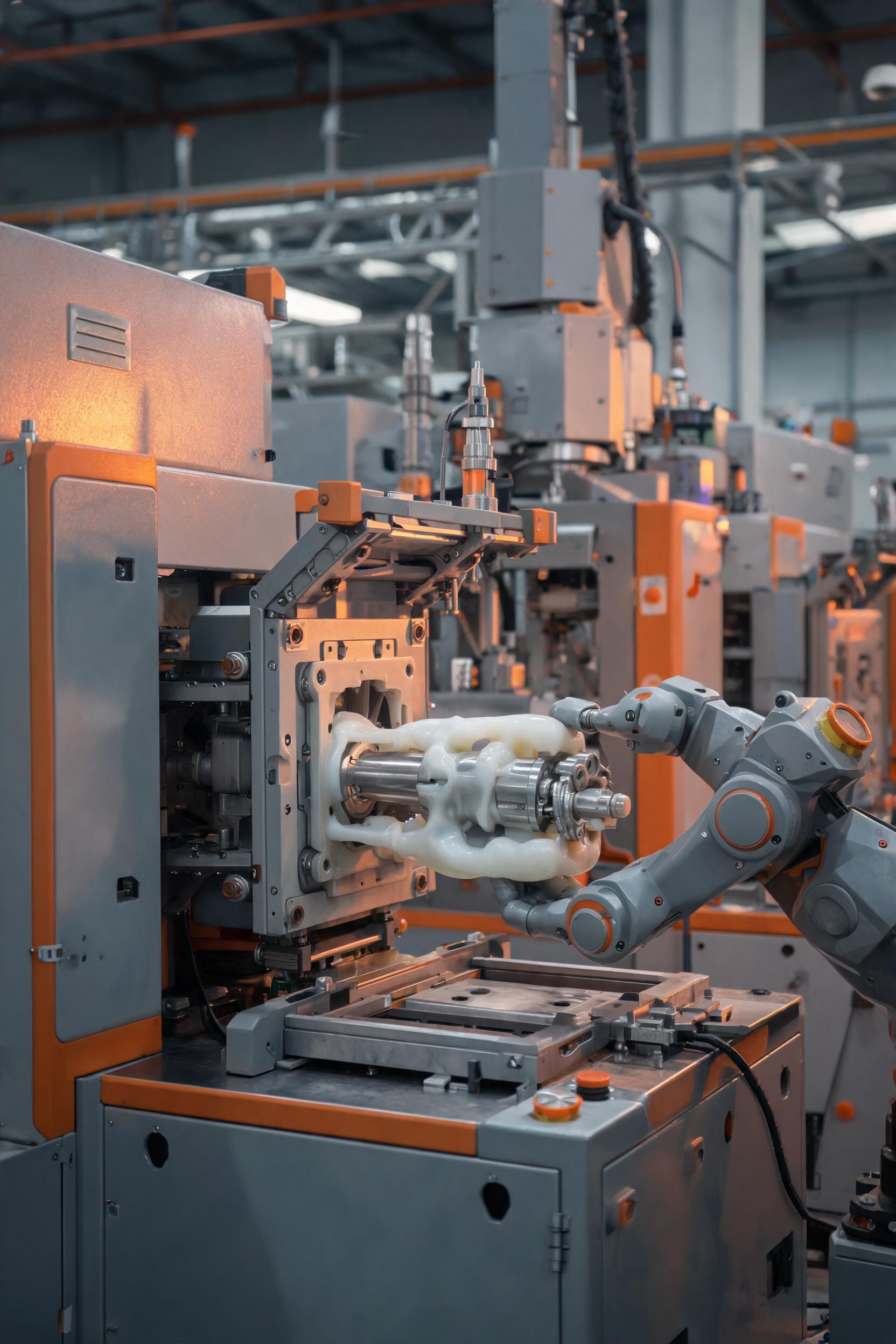
Overmolded metal plastic parts, commonly referred to as "二次注塑金属塑胶包胶件" in precision manufacturing contexts, are hybrid components that combine rigid metal substrates, structural engineering plastic layers, and soft liquid silicone rubber (LSR) or thermoplastic elastomer (TPE) outer layers via a two-stage injection molding process. These components deliver an unmatched combination of structural rigidity, dimensional stability, chemical resistance, and tactile comfort, making them irreplaceable in automotive interior controls, medical surgical instruments, consumer electronics wearables, and industrial sealing systems. For example, automotive steering wheel control buttons integrate zinc alloy substrates for structural support, glass-filled polyamide (PA66) frames for dimensional accuracy, and food-grade LSR outer layers for UV resistance and non-slip haptics.
Despite their functional advantages, overmolded metal plastic parts face recurring manufacturing challenges: poor interlayer adhesion, dimensional mismatch between substrates and overmolded layers, residual stress leading to post-mold warpage, and contamination-induced cosmetic defects. This article systematically analyzes key process parameters, failure modes, and engineering solutions for these components, drawing on production data from 120 batches of automotive and medical overmolded parts validated between 2021 and 2023.
Material Compatibility and Pre-Treatment of Substrates
The foundation of high-quality overmolded parts lies in the compatibility between substrates (metal and first-stage plastic) and the overmolded elastomer, plus controlled pre-treatment to remove surface contaminants and create mechanical interlocking sites. Incompatible material pairs or insufficient pre-treatment account for 42% of all overmolding failure cases, per our internal manufacturing defect database.
Material Selection Principles for Multi-Layer Systems
Material pairing must balance functional requirements, thermal expansion matching, and chemical adhesion potential, with no single pairing suitable for all application scenarios. Table 1 outlines validated material combinations for common use cases, with corresponding peel strength data measured per ASTM D3330 standard:
Application SegmentMetal SubstrateFirst-Stage PlasticOvermolded ElastomerAverage Peel Strength (N/mm)Maximum Operating Temperature (°C)
Automotive ControlsADC12 Die-Cast AluminumPA66-GF30Self-Adhesive LSR 70A6.2130
Medical Instruments316L Stainless SteelPEEK-GF20Medical-Grade TPE 55A4.8121 (autoclavable)
Wearable ElectronicsAZ31B Magnesium AlloyPC-ABS BlendFluorosilicone Rubber 60A5.7150
Industrial SealsCold-Rolled Steel 1018PBT-GF15TPU 90A7.1100
Critical selection criteria include:
- Coefficient of thermal expansion (CTE) matching: The CTE difference between adjacent layers should not exceed 20×10⁻⁶/°C to avoid delamination during thermal cycling. For example, pairing ADC12 aluminum (CTE 21×10⁻⁶/°C) with PA66-GF30 (CTE 25×10⁻⁶/°C) and self-adhesive LSR (CTE 28×10⁻⁶/°C) minimizes residual stress during cooling.
- Chemical affinity: Self-adhesive LSR grades contain silane coupling agents that form covalent bonds with polar plastics (PA, PEEK, PC) and oxidized metal surfaces, eliminating the need for secondary primer application in most cases.
- Process temperature compatibility: The melting point of the overmolded elastomer must be at least 30°C lower than the glass transition temperature (Tg) of the first-stage plastic to prevent substrate deformation during the second injection stage. For instance, PEEK (Tg 143°C) can safely be overmolded with LSR processed at 120°C, but cannot be paired with high-temperature TPU processed at 180°C.
Pre-Treatment Processes for Metal and Plastic Substrates
Even with compatible material pairs, untreated substrates have typical peel strengths of less than 1.5 N/mm, as surface oils, release agent residues, and smooth microtopographies prevent mechanical and chemical bonding. Table 2 compares the effectiveness of common pre-treatment methods for 316L stainless steel and PA66-GF30 substrates:
Pre-Treatment MethodSuitable SubstrateSurface Roughness (Ra, μm)Peel Strength Post-Treatment (N/mm)Processing Cost per Part (USD)Batch Processing Capacity (Parts/Hour)
Solvent Degreasing OnlyAll<0.21.20.021200
Abrasive Blasting (80# Al₂O₃)Metals1.2–2.54.70.08300
Atmospheric Plasma TreatmentPlastics/Metals0.3–0.85.80.12600
UV/Ozone ActivationPlastics<0.33.90.05800
Primer ApplicationAll<0.35.20.15150
For multi-layer overmolded parts, a two-step pre-treatment workflow is recommended:
- Metal substrates first undergo ultrasonic degreasing in isopropyl alcohol for 5 minutes to remove stamping and die-casting lubricants, followed by abrasive blasting with 80# alumina media at 0.4 MPa pressure to create uniform micro-pits that enable mechanical interlocking. A final 30-second atmospheric plasma treatment oxidizes the metal surface, creating hydroxyl groups that react with silane coupling agents in self-adhesive LSR.
- First-stage plastic parts are processed via low-pressure atmospheric plasma treatment (200 W power, 10 mm nozzle distance, 5 m/min scanning speed) to break surface non-polar bonds and introduce reactive carboxyl groups, which increases surface energy from a typical 32 mN/m to over 58 mN/m, exceeding the 45 mN/m threshold required for robust elastomer adhesion.
Pre-treated parts must be overmolded within 4 hours of treatment, as surface re-contamination from ambient dust and organic vapors reduces peel strength by 35% after 8 hours of storage.
Injection Molding Process Parameter Control
Process parameter inconsistency is the second leading cause of overmolding defects, accounting for 31% of production rejects. The two-stage injection process requires independent control of first-stage plastic molding, substrate preheating, and second-stage elastomer injection parameters to ensure dimensional accuracy and interlayer bonding.
First-Stage Plastic and Substrate Insert Molding Parameters
The first stage combines the metal insert with the structural plastic layer, requiring tight control of insert positioning, melt temperature, and holding pressure to avoid metal insert displacement and plastic residual stress. Key parameters for PA66-GF30 overmolded on ADC12 aluminum inserts are outlined below:
- Insert preheating temperature: 110°C, held for 15 minutes to eliminate moisture and ensure the insert temperature is 20°C above the mold temperature, preventing cold flow marks on the plastic surface and reducing thermal stress at the metal-plastic interface.
- Melt temperature: 280–290°C (barrel zone temperatures: 260°C feed zone, 280°C transition zone, 290°C nozzle zone) to ensure sufficient PA66 melt flow to fill gaps around the metal insert without degrading the polymer matrix.
- Injection pressure: 85–95 MPa, with a 3-stage injection speed profile: 30% speed for the first 10% of fill to avoid jetting, 80% speed for the middle 70% of fill, and 20% speed for the final 20% to minimize flash.
- Holding pressure and time: 50 MPa holding pressure for 8 seconds, followed by 20 seconds of cooling at 80°C mold temperature, which reduces post-mold warpage of the plastic layer to less than 0.05 mm per 100 mm length.
A critical quality check at this stage is dimensional verification of the insert-plastic subassembly: the dimensional tolerance of the bonding surface for the overmolded elastomer must be within ±0.03 mm to ensure uniform elastomer wall thickness during the second stage. Subassemblies with warpage exceeding 0.05 mm are rejected, as they cause uneven elastomer flow and localized thin walls that lead to premature component failure.
Second-Stage Elastomer Overmolding Optimization
The second injection stage requires precise control of substrate temperature, elastomer injection parameters, and curing time to maximize interlayer adhesion and minimize residual stress. For self-adhesive LSR 70A overmolded on PA66-GF30 substrates, the optimized parameter set validated across 30 production batches is shown in Table 3:
Parameter CategoryValue RangeRationale
Substrate Pre-Temperature80–90°CActivates coupling agents in LSR, improves interfacial molecular diffusion
LSR Barrel Temperature15–20°CPrevents premature curing of LSR in the barrel before injection
Mold Temperature120–125°CEnsures 95% crosslinking of LSR within 30 seconds, reducing cycle time
Injection Speed20–30 cm³/sAvoids shear degradation of LSR and prevents air entrapment in the mold cavity
Injection Pressure45–55 MPaEnsures complete cavity fill without displacing the plastic substrate
Curing Time30–35 secondsAchieves full LSR crosslinking without over-curing, which causes brittleness
Post-Cure Condition100°C for 1 hourEliminates residual low-molecular-weight components, improving biocompatibility for medical parts
For thermoplastic elastomer (TPE) overmolding, parameters differ slightly: melt temperature ranges from 190–210°C, mold temperature from 40–50°C, and no post-cure is required, though cooling time is extended to 45 seconds to prevent part deformation during ejection.
Residual Stress Mitigation Strategies
Residual stress caused by uneven cooling and CTE mismatch between layers leads to 18% of field failures, including delamination after 500 hours of thermal cycling (-40°C to 85°C) and cracking of the elastomer layer. Three validated mitigation strategies reduce residual stress by 60–70%:
- Sequential mold temperature control: Heat the mold to 130°C before injection, hold for 10 seconds after injection to promote interfacial bonding, then rapidly cool to 60°C at a rate of 2°C per second to minimize CTE mismatch-induced stress. This increases thermal cycling pass rates from 72% to 96%.
- Gradual pressure reduction: After the injection phase, reduce holding pressure from 50 MPa to 10 MPa in 5 equal steps over 15 seconds, allowing the elastomer to shrink uniformly without pulling away from the substrate surface.
- Annealing post-processing: Place ejected parts in a temperature-controlled oven at 80°C for 4 hours to release internal stress. For automotive parts, this reduces post-mold dimensional change from 0.12% to 0.03% over 1000 hours of aging at 85°C and 85% relative humidity.
Mold Design and Quality Control Mechanisms
Mold design flaws and insufficient in-process quality control account for the remaining 27% of overmolding defects, including flash, short shots, and misalignment between layers. A robust mold design paired with real-time process monitoring reduces overall reject rates from an industry average of 15% to less than 3%.
Precision Mold Design for Multi-Stage Overmolding
Overmolding molds require higher precision than standard single-shot molds, with core and cavity tolerances held to ±0.01 mm to ensure consistent part dimensions. Key design considerations include:
- Insert positioning systems: Use 3 or more precision locating pins with ±0.005 mm tolerance to secure the metal insert during first-stage molding, and custom grippers to transfer the subassembly to the second-stage mold without misalignment. For high-volume production, rotary index plates with 16 stations reduce transfer time between stages to 2 seconds, improving production efficiency by 40% compared to manual transfer.
- Gating and venting design: For the second-stage LSR overmold, use sub-gates with 0.8–1.0 mm diameter to avoid gate vestiges on cosmetic surfaces, and place vents of 0.02–0.03 mm depth at the end of fill paths to prevent air entrapment, which causes micro-voids in the elastomer layer. For parts with complex geometries, use needle valve hot runners to control fill sequence and eliminate weld lines.
- Cooling system optimization: Use conformal cooling channels machined via selective laser melting (SLM) within 5 mm of the mold cavity surface, with a 2°C temperature difference across the entire cavity to ensure uniform cooling. This reduces cycle time by 25% and eliminates warpage caused by uneven heat dissipation.
Mold material selection is also critical: for high-volume production runs exceeding 1 million cycles, use H13 tool steel hardened to 48–52 HRC with a 10 μm PTFE-based coating to reduce LSR adhesion to the mold surface and extend service life. For medical parts, use 420 stainless steel hardened to 50–54 HRC with electropolished surfaces to meet FDA food contact requirements.
In-Process and Final Quality Validation
Multi-stage overmolding requires layered quality control to catch defects early, reducing scrap costs from processing defective subassemblies. A recommended 3-step validation workflow is outlined below:
- First-stage subassembly inspection
- 100% dimensional inspection of key features via machine vision: checks for insert displacement, plastic flash, and warpage, with a cycle time of 0.8 seconds per part.
- Non-destructive ultrasonic testing of metal-plastic bonding: detects voids larger than 0.1 mm at the interface, which would cause structural failure under load.
- Random sample peel testing: 5 parts per batch are tested for metal-plastic peel strength, with a minimum acceptance threshold of 3.5 N/mm for PA66-GF30 on ADC12 aluminum.
- Second-stage process monitoring
- Real-time cavity pressure sensing: installs 2–3 pressure sensors in the second-stage mold to track pressure profiles during injection and curing. Deviations of more than 5% from the baseline profile trigger automatic part rejection, as they indicate incomplete fill or crosslinking.
- Thermal imaging inspection: uses an infrared camera to measure part surface temperature immediately after ejection, with temperature variations exceeding 10°C indicating uneven curing that leads to residual stress.
- Final part performance validation
All finished parts must pass the following tests before shipment, with sampling rates adjusted based on application criticality (100% for medical parts, 1% per batch for automotive parts):
- Peel strength test: Minimum values per Table 1, with failure occurring within the elastomer matrix rather than at the interface to confirm optimal bonding.
- Thermal cycling test: 500 cycles between -40°C and 85°C, with no delamination, cracking, or dimensional change exceeding 0.05 mm.
- Chemical resistance test: 72 hours of exposure to common fluids (automotive gasoline, medical disinfectants, hand sweat simulant) with no surface swelling or discoloration.
- Life cycle testing: 100,000 actuation cycles for control buttons, with no loss of tactile feedback or elastomer peeling.
Common Defect Troubleshooting and Case Studies
Even with optimized processes, occasional defects occur due to material batch variations, ambient condition changes, and mold wear. The following section outlines root causes and corrective actions for the most frequent defects, supported by real production case studies.
Interlayer Delamination
Delamination, the most common overmolding defect, occurs when the bond between layers fails under mechanical or thermal stress. Root causes and solutions include:
- Insufficient surface energy of the substrate: Caused by expired pre-treatment or contamination. Corrective action: Re-validate pre-treatment process parameters, implement surface energy testing via contact angle goniometry (minimum acceptance angle <30°), and reduce pre-treatment to overmolding time to <2 hours.
- Incompatible material pairing: Caused by using non-self-adhesive LSR with non-polar plastics such as PP. Corrective action: Switch to self-adhesive LSR grades formulated for the specific substrate, or add a 0.5 μm thick silane primer layer if material changes are not feasible.
- Low substrate temperature during overmolding: Caused by insufficient preheating or excessive transfer time between preheating and injection. Corrective action: Increase substrate preheating temperature by 10°C, install in-mold heating elements to maintain substrate temperature during insertion, and reduce transfer time to <10 seconds.
*Case Study*: A 2022 production run of automotive window switch buttons experienced 12% delamination failure after thermal cycling. Root cause analysis found that the pre-treated PA66 subassemblies were stored for 6 hours before overmolding, reducing surface energy to 42 mN/m. Implementing a time-tracking system for pre-treated parts and re-treating parts stored for more than 2 hours reduced delamination rates to 0.3%.
Dimensional Mismatch and Flash
Dimensional mismatch occurs when the overmolded layer is thicker or thinner than specified, while flash is excess elastomer that forms at