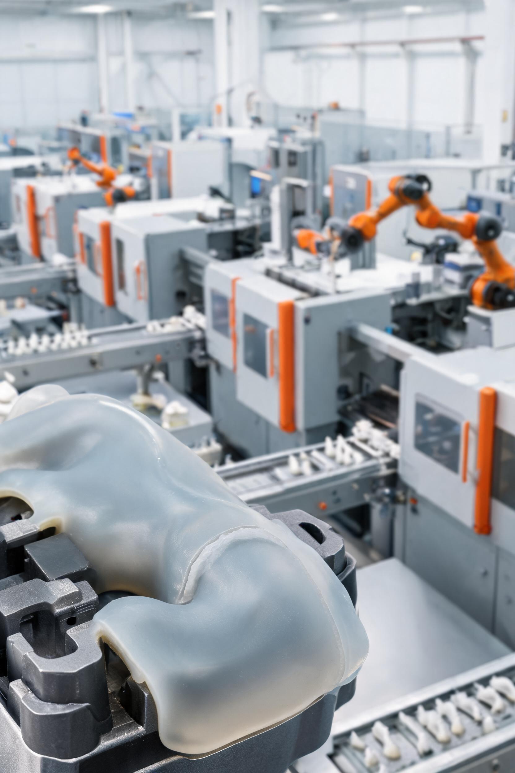
Liquid silicone rubber (LSR) overmolding, known as 二次注塑包胶 in Chinese manufacturing contexts, is a precision multi-material injection molding process that bonds cured LSR to a rigid or semi-rigid substrate (typically thermoplastics, metals, or glass) in a sequential two-shot operation. Unlike manual adhesive bonding or insert molding with pre-formed substrates, LSR overmolding integrates the substrate fabrication and LSR curing steps into a single automated production cycle, delivering superior bond strength, dimensional consistency, and production efficiency for medical devices, consumer electronics, automotive components, and industrial sealing products. The process leverages LSR’s unique properties: extreme temperature resistance (-60°C to 220°C), biocompatibility, low compression set, and soft-touch ergonomics, while combining them with the structural rigidity of engineering substrates. However, successful implementation requires strict control over material compatibility, tooling design, and process parameters to avoid common defects such as delamination, flash, incomplete filling, and substrate deformation. This article systematically breaks down the core technical considerations of LSR overmolding, analyzes root causes of frequent production issues, and provides empirically validated solutions for high-yield manufacturing.
Material Compatibility and Pre-Processing Requirements
The foundation of a successful LSR overmolding bond lies in the chemical and physical compatibility between the LSR formulation and the substrate material. Unlike thermoplastic overmolding, which relies on melting and interdiffusion of substrate surfaces, LSR overmolding forms bonds through a combination of mechanical interlocking, chemical adhesion between reactive LSR functional groups and substrate surface moieties, and interdiffusion of LSR precursors into pre-treated substrate surfaces. Incompatible material pairs or insufficient pre-treatment will lead to immediate or long-term delamination, even if process parameters are optimized.
Substrate Material Selection and Compatibility Validation
Not all engineering materials are suitable for LSR overmolding, as bond performance varies drastically based on the substrate’s surface energy, chemical resistance, and thermal stability. Table 1 summarizes the bond performance of common substrate materials with standard medical-grade LSR, including recommended pre-treatment methods and typical application scenarios.
Substrate MaterialSurface Energy (mN/m)Typical Bond Strength (MPa)Recommended Pre-TreatmentCommon Applications
PC (Polycarbonate)42–462.8–3.5Plasma activationWearable device housings, medical device enclosures
PBT (Polybutylene Terephthalate)38–422.2–2.8Flame treatment, primer coatingAutomotive sensor seals, electrical connector grommets
PA6/PA66 (Polyamide)39–451.8–2.5Plasma activation + moisture pre-conditioningPlumbing valve seals, industrial handle grips
ABS (Acrylonitrile Butadiene Styrene)35–401.5–2.2Corona treatmentConsumer electronics button pads, toy components
Aluminum 606132–362.5–3.2Anodization + silane primer coatingMedical surgical instrument grips, heat sink seals
PP (Polypropylene)29–330.3–0.8*Flame treatment + adhesive primerFood container seals, automotive interior trim
*Bond strength of untreated PP is below 0.5 MPa, requiring custom self-adhesive LSR formulations to reach 2.0 MPa or higher.
Thermal stability of the substrate is another critical selection criterion: LSR curing typically requires mold temperatures between 150°C and 200°C, so substrates must have a heat deflection temperature (HDT) at 1.8 MPa of at least 10°C higher than the LSR curing temperature to avoid deformation during the second injection step. For example, general-purpose ABS has an HDT of 90–95°C, making it unsuitable for overmolding with high-temperature LSR grades that cure at 180°C; in such cases, heat-resistant ABS grades with HDT > 190°C are required.
For material pair validation, manufacturers should conduct standardized lap shear tests per ASTM D1002, followed by accelerated aging tests (1000 hours at 85°C/85% relative humidity, or 100 thermal cycles between -40°C and 120°C) to ensure long-term bond integrity for harsh-environment applications. Self-adhesive LSR grades, which incorporate silane coupling agents or reactive acrylic functional groups in their formulation, eliminate the need for external primers for most thermoplastic substrates, reducing production steps and volatile organic compound (VOC) emissions, but require 5–10% longer curing times to complete the cross-linking reaction with the substrate surface.
Substrate Pre-Treatment Process Optimization
Even for inherently compatible material pairs, surface contaminants (release agents, machining oils, dust, or oxidation layers) on the substrate will reduce bond strength by 50% or more, making pre-treatment a mandatory step for high-yield production. The following pre-treatment methods are ranked by effectiveness for LSR overmolding applications:
- Low-pressure atmospheric plasma treatment: The most widely used method for mass production, which bombards the substrate surface with high-energy oxygen or argon plasma to remove organic contaminants, increase surface energy by 10–15 mN/m, and introduce reactive hydroxyl and carboxyl groups that form covalent bonds with LSR. For PC substrates, 30–60 seconds of plasma treatment at 2–3 kW power increases the water contact angle from 80° to <30°, and improves bond strength by 2–3 times compared to untreated samples.
- Flame treatment: Suitable for polyolefin substrates (PP, PE) with low surface energy, which uses an oxidizing flame (air-fuel ratio of 10:1 to 12:1) to introduce polar functional groups on the substrate surface. The treatment distance must be controlled between 10–15 cm, and exposure time limited to 1–2 seconds to avoid substrate warping.
- Solvent cleaning + primer coating: For metal and glass substrates, ultrasonic cleaning with isopropyl alcohol (IPA) removes machining residues, followed by a thin (5–10 μm) layer of silane primer that acts as a coupling agent between the inorganic substrate surface and the organic LSR. Excess primer must be wiped off before curing to avoid weak boundary layers that reduce bond strength.
- Surface texturing: For high-stress applications, micro-roughening of the substrate surface (Ra = 1.6–3.2 μm, achieved via laser etching or mold texture) creates mechanical interlocking features that increase bond strength by an additional 30–40% when combined with chemical pre-treatment.
Pre-treatment efficacy should be verified via inline water contact angle testing immediately before the overmolding step: a consistent contact angle below 40° is required for reliable bonding, and substrates with contact angles above 50° should be re-treated or discarded.
Tooling Design and Precision Control for LSR Overmolding
LSR’s low viscosity (100–1000 Pa·s during injection, 100–1000 times lower than thermoplastics) and high curing shrinkage (2–3% for unfilled grades, 0.5–1% for filled grades) impose unique requirements on tooling design, far stricter than those for single-shot thermoplastic molding. Poor tooling design is responsible for 60% of recurring LSR overmolding defects, including flash, incomplete filling, and substrate misalignment.
Gating and Runner System Design
LSR’s low viscosity means it can flow through gaps as small as 5 μm, making flash prevention a core priority in gating design. Unlike thermoplastic runners, which use cold runners that solidify between cycles, LSR overmolding tools use heated runners to keep the material in a liquid state before injection, reducing material waste by 30–50% compared to cold runner systems.
For the substrate (first-shot) tool, gating should be positioned to minimize residual stress in areas that will be covered by LSR, as residual stress can lead to substrate cracking during the high-temperature LSR curing step. Sub-submarine gates (diameter 0.8–1.2 mm) are recommended for most thermoplastic substrates, as they leave minimal gate vestiges that could interfere with LSR bonding.
For the LSR (second-shot) tool, the following gating options are commonly used, selected based on part geometry and aesthetic requirements:
- Pinpoint gates: Diameter 0.4–0.8 mm, suitable for small parts (weight <5 g) such as keypad buttons and small seals. Gate vestiges are minimal, requiring no post-processing, but may cause shear heating of LSR if the length-to-diameter ratio exceeds 3:1.
- Edge gates: Width 1.5–3 mm, thickness 0.3–0.5 mm, ideal for flat parts such as gasket seals and ergonomic grips. They provide uniform flow with minimal shear stress, reducing the risk of LSR degradation, but leave a small gate mark that may require trimming.
- Sub-gates: Positioned on the underside of the substrate, hidden from view, making them suitable for consumer-facing parts. The gate breaks automatically during part ejection, eliminating manual trimming steps.
Critical runner system parameters for LSR overmolding include:
- Runner diameter: 3–8 mm, sized to keep LSR flow velocity below 0.5 m/s to avoid shear-induced curing and air entrapment
- Heated runner temperature control: ±1°C accuracy, set 10–20°C below the LSR curing temperature to prevent premature cross-linking in the runner
- Venting depth: 0.005–0.01 mm at the end of fill, as LSR’s low viscosity will cause flash if vents are deeper than 0.012 mm, while insufficient venting leads to trapped air and incomplete filling.
Substrate Positioning and Temperature Control System
Misalignment of the substrate in the second-shot mold cavity is a common defect that leads to uneven LSR wall thickness and exposed substrate areas, especially for parts with LSR thickness below 0.5 mm. To ensure positional accuracy within ±0.02 mm, tool designers should implement the following features:
- Precision locating features: Integrate 2–3 hardened steel locating pins (tolerance H7/g6) that mate with alignment holes molded into the first-shot substrate, avoiding reliance on outer part edges which may have dimensional variation from thermoplastic shrinkage.
- Vacuum suction channels: For thin or flexible substrates (thickness <1 mm), add 0.5–1 mm diameter vacuum holes on the cavity surface to hold the substrate flat during LSR injection, preventing movement caused by LSR flow pressure.
- Interference-fit sealing ribs: Add 0.05–0.1 mm high ribs around the perimeter of the substrate bonding area, which compress slightly when the mold closes to create a seal that prevents LSR from flowing onto non-overmolded substrate surfaces.
Temperature control is another critical tooling design factor, as LSR curing requires uniform cavity temperature to ensure consistent cross-linking, while the substrate side of the tool must be kept cool enough to prevent substrate deformation. For two-shot rotary mold systems, which are the most common setup for high-volume LSR overmolding, the first-shot (substrate) cavity is maintained at 40–80°C for thermoplastic cooling, while the second-shot (LSR) cavity is heated to 150–200°C using cartridge heaters with ±2°C temperature uniformity across the cavity surface. For tools larger than 300 mm x 300 mm, multiple independent heating zones should be used to compensate for heat loss at the tool edges, and thermal insulation plates (10–15 mm thick) should be installed between the two cavity sets to prevent heat transfer from the LSR side to the thermoplastic side.
For low-volume production with single-shot molds using manual substrate insertion, thermocouples should be embedded in the cavity to monitor actual surface temperature, as air gaps between the substrate and cavity wall can reduce heat transfer by 20–30%, leading to under-cured LSR and low bond strength.
LSR Overmolding Process Parameter Tuning
Even with compatible materials and optimized tooling, incorrect process parameters will lead to inconsistent part quality and low production yield. LSR overmolding is a dynamic process where injection parameters, curing conditions, and substrate insertion timing must be tightly synchronized to ensure optimal bond formation and defect-free parts.
Injection and Curing Parameter Optimization
LSR is a two-component (A/B) system that cures via platinum-catalyzed addition reaction when heated, so process parameters must be adjusted to ensure complete filling of the cavity before cross-linking begins, followed by sufficient curing time to achieve full mechanical properties and bond strength. Table 2 lists the standard parameter ranges for medical-grade LSR overmolding on PC substrates, with recommended tolerance limits for high-yield production.
Process ParameterStandard RangeTolerance LimitImpact of Out-of-Range Operation
A/B component mix ratio1:1±2%Off-ratio mixes cause under-curing (excess A) or over-curing (excess B), reducing bond strength by 30% or more
Injection pressure60–120 bar±5 barLow pressure leads to incomplete filling; high pressure causes substrate deformation and flash
Injection speed3–10 cm³/s±1 cm³/sHigh speed causes shear heating and premature curing; low speed leads to flow marks and air entrapment
Holding pressure20–40 bar±3 barInsufficient holding pressure leads to sink marks and high shrinkage; excessive pressure causes substrate bending
Mold temperature160–180°C±3°CLow temperature causes under-curing and poor adhesion; high temperature leads to LSR degradation and substrate warping
Curing time30–60 s per mm of LSR thickness±5 sInsufficient curing leads to low bond strength and high compression set; excessive curing reduces production efficiency and may cause substrate discoloration
Material barrel temperature15–25°C±2°CHigh barrel temperature causes premature curing in the feed system; low temperature increases LSR viscosity, leading to filling defects
For substrates with low HDT, such as general-purpose ABS, a step-curing process can be used to reduce thermal stress: first inject LSR at a lower mold temperature (140–150°C) for 50% of the total curing time, then increase the temperature to 170°C for the remaining curing time. This process reduces initial heat exposure for the substrate, lowering deformation risk by 70% compared to constant high-temperature curing, while maintaining 90% of the bond strength of standard curing.
In-line curing monitoring can be implemented via cavity pressure sensors: the pressure in the LSR cavity increases during injection, stabilizes during holding, and drops slightly as LSR cross-links. A consistent pressure drop of 5–10 bar during curing indicates complete cross-linking, and parts with a pressure drop below 3 bar should be flagged as under-cured and rejected.
Process Synchronization and Defect Prevention
LSR overmolding involves multiple sequential steps, and even small timing errors can lead to costly defects. The most time-sensitive step is the transfer of the first-shot substrate to the second-shot cavity: the time between substrate ejection from the first mold and insertion into the second mold should be kept below 30 seconds for unprimed substrates, as surface energy degrades over time after pre-treatment. For plasma-treated PC substrates, surface energy drops by 20% after 1 hour of exposure to ambient air, and by 50% after 24 hours, making immediate overmolding critical for consistent bond strength.
Another common synchronization issue is mold closing speed: the mold should close at 10–20 mm/s when approaching the substrate, to avoid damaging or dislodging the substrate, then increase to 50–100 mm/s for final locking. A buffer pressure of 10–15 bar should be applied during the final 5 mm of mold closing to ensure the sealing ribs on the substrate are properly compressed, preventing flash.
For two-shot rotary machines, the rotary table indexing accuracy must be maintained at ±0.01 mm, as even 0.05 mm of misalignment will lead to uneven LSR wall thickness. Regular calibration of the rotary table encoder every 10,000 cycles is recommended to prevent drift.
Common LSR Overmolding Defects and Root Cause Solutions
Despite careful material, tooling, and process design, manufacturers frequently encounter recurring defects in LSR overmolding production. The following section analyzes the four most common defects, their root causes, and validated corrective actions based on field data from 20+ LSR overmolding production lines.
Delamination and Poor Bond Strength
Delamination, where the LSR layer separates from the substrate either immediately after molding or during end-use, is the most critical quality issue for overmolded parts, as it compromises both functional performance (e.g., sealing, ergonomics) and structural integrity. The primary root causes and solutions are:
- Inadequate surface pre-treatment: If bond strength is consistently low across all parts, verify the water contact angle of pre-treated substrates; if it exceeds 40°, increase plasma treatment time by 10–20 seconds, or replace worn plasma electrodes (which have a typical service life of 500 hours). For primer-coated substrates, check for expired primer or uneven coating thickness, which creates weak boundary layers.
- Incompatible material pair: If lap shear strength is below 1 MPa even with optimal pre-treatment, switch to a self-adhesive LSR grade formulated for the specific substrate, or add a thin tie layer of compatible thermoplastic on the substrate bonding area during first-shot molding.
- Under-cured LSR: If the LSR layer is tacky to the touch and delaminates easily, increase curing time by 10–15 seconds, or raise mold temperature by 5–10°C. Verify the A/B mix ratio using a gravimetric test, as off-ratio mixing is a common hidden cause of under-curing.
- Contaminated substrate surface: If delamination occurs randomly on 5–10% of parts, check for residual release agent on the first-shot mold cavity, or oil contamination from the machine gripper used to transfer substrates. Implement inline ionized