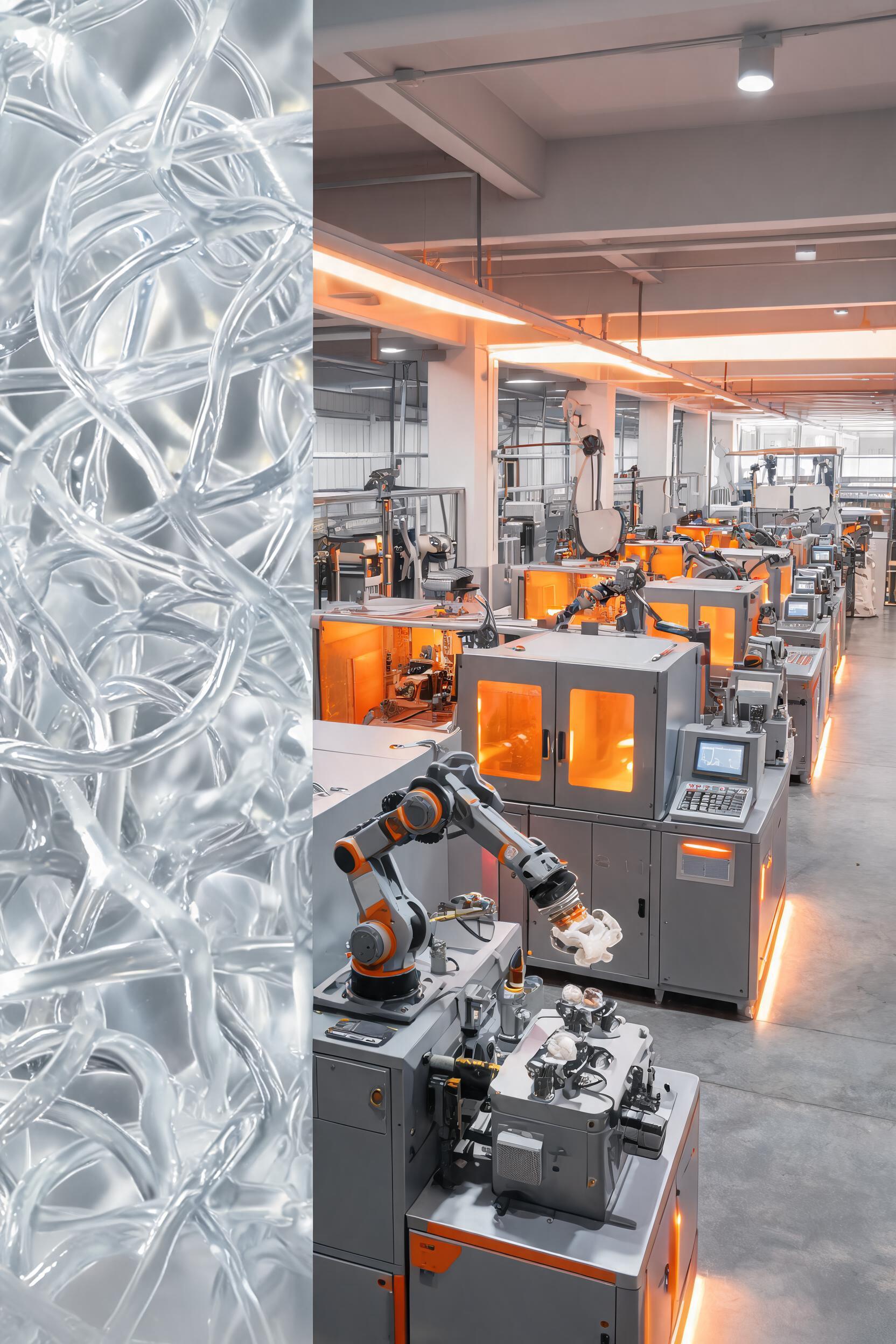
Liquid silicone rubber (LSR) has emerged as a high-performance material of choice across medical, automotive, consumer electronics, and aerospace sectors due to its exceptional thermal stability (-60°C to 220°C operating range), biocompatibility (ISO 10993 and USP Class VI certification eligibility), electrical insulation resistance (10¹⁴ Ω·cm volume resistivity), and long-term resistance to UV radiation and chemical exposure. Liquid silicone injection molding, the dominant processing technology for high-volume LSR component manufacturing, differs fundamentally from thermoplastic injection molding due to LSR’s thermoset curing mechanism, low raw material viscosity, and strict requirements for process parameter control. This analysis provides a technical deep dive into the entire LSR injection molding workflow, from material preparation to post-processing, quantifies key process parameters, and evaluates defect mitigation strategies and emerging technological advancements to support manufacturers in optimizing production yield, part quality, and operational efficiency.
Core Raw Material Characteristics and Pre-Processing Requirements for LSR Molding
LSR is a two-component platinum-catalyzed thermoset elastomer, typically supplied as Part A (containing platinum catalyst and vinyl-functional polydimethylsiloxane) and Part B (containing methyl-hydrogen siloxane crosslinker and reaction inhibitors). Unlike thermoplastics, which rely on heat-induced melting and cooling-induced solidification, LSR cures via an exothermic hydrosilylation reaction when exposed to elevated temperatures, forming a permanently crosslinked three-dimensional polymer network. The inherent properties of LSR raw materials directly define the unique constraints of the injection molding process.
Key Material Property Specifications for Molding-Grade LSR
Molding-grade LSR formulations are engineered with targeted properties to suit specific application requirements, with critical parameters that directly impact processing behavior outlined in Table 1.
ParameterTypical Range for Molding-Grade LSRProcess Relevance
Viscosity (25°C, pre-cure)10,000 – 2,000,000 cPLower viscosity materials improve flow for micro-cavity or thin-wall parts but increase risk of flash; higher viscosity materials reduce flash potential but require higher injection pressure
Shore Hardness (A Scale)10 – 80Softer grades (10–30A) are used for sealing and wearable components; harder grades (50–80A) for structural and high-load applications
Pot Life (25°C, post-mixing)3 – 72 hoursDefines the maximum allowable residence time of mixed material in the dosing system before partial curing causes process instability
Curing Time (150°C, 2mm wall thickness)10 – 45 secondsShorter curing times improve production throughput but require uniform mold temperature distribution to avoid under-cure
Tensile Strength (cured)5 – 12 MPaDetermines the demolding force required, with lower strength materials at higher risk of tearing during ejection
Linear Mold Shrinkage2.0 – 3.5%Must be accounted for in mold cavity design to meet part dimensional tolerances
Pre-Molding Material Preparation and Quality Control
Inconsistent material preparation is the root cause of 32% of LSR molding defects, per a 2023 industry survey of 120 medical LSR component manufacturers. The pre-processing workflow requires strict adherence to the following steps to ensure process repeatability:
- Material Storage: Unopened Part A and Part B drums must be stored at 15–25°C, away from direct sunlight and sources of sulfur, tin, or amine compounds, which can poison the platinum catalyst and prevent full curing. Refrigerated storage is not recommended, as condensation can introduce moisture that causes micro-porosity in finished parts.
- Degassing: Both components are individually degassed under vacuum (< -0.09 MPa) for 15–30 minutes prior to mixing to remove entrained air introduced during drum transportation and handling. For high-precision applications such as microfluidic chips, a secondary degassing step post-mixing is required to reduce air bubble content to < 0.1% by volume.
- Precision Metering and Mixing: A positive-displacement dosing system with ±0.5% metering accuracy is required to deliver Part A and Part B at the specified ratio (typically 1:1 by weight, though some specialty formulations use 10:1 ratios). The materials are mixed in a static mixer with 12–20 mixing elements to ensure homogeneous dispersion of catalyst and crosslinker; insufficient mixing leads to localized under-cure or over-cure defects.
- In-Line Viscosity Monitoring: For high-volume production lines, in-line rotational viscometers are integrated into the dosing system to continuously verify mixed material viscosity. A viscosity deviation of > 10% from the baseline specification triggers an automatic process stop to prevent defective parts from entering downstream production.
Process Parameter Optimization for High-Quality LSR Injection Molding
The LSR injection molding process can be divided into four interconnected stages: injection, compression, curing, and demolding. Each stage has interdependent parameters that must be balanced to achieve dimensional accuracy, avoid defects, and maximize production throughput. Unlike thermoplastic molding, where barrel temperatures are elevated to melt material, LSR processing uses cooled barrels to prevent premature curing and heated molds to trigger crosslinking, creating a unique set of control requirements.
Injection Stage Parameter Tuning
The injection stage involves delivering mixed LSR from the cooled barrel into the closed mold cavity, with parameters optimized to ensure complete cavity filling without introducing shear stress that could affect curing behavior or cause flash.
- **Barrel Temperature Profile: The barrel is divided into 3–4 temperature zones, all maintained between 5°C and 25°C to suppress premature curing. The feed zone (closest to the dosing system) is typically set to 5–10°C, with a gradual temperature increase to 20–25°C at the nozzle to reduce material viscosity and improve flow. A temperature deviation of > 5°C in any barrel zone can reduce material pot life by 40% or more.
- **Injection Pressure and Flow Rate: Typical injection pressures range from 50 to 150 bar, significantly lower than the 800–2500 bar used for thermoplastic molding, due to LSR’s low pre-cure viscosity. The optimal injection flow rate is determined by the part’s wall thickness: for thin-wall parts (< 0.5 mm), a high flow rate (50–100 cm³/s) is used to fill the cavity before curing initiates, while for thick-wall parts (> 5 mm), a lower flow rate (10–30 cm³/s) prevents air entrapment. Shear rates during injection must be kept below 10,000 s⁻¹ to avoid shear-induced degradation of the platinum catalyst, which can cause uneven curing.
- **Nozzle and Cold Runner Design: A shut-off nozzle with a 0.8–2.5 mm diameter orifice is used to prevent material leakage between injection cycles. For multi-cavity molds, cold runner systems (maintained at 10–15°C) are preferred to keep the feed material in an uncured state, reducing material waste by up to 75% compared to hot runner systems, which cure runner material between cycles. Cold runner channels are typically polished to a Ra < 0.2 μm to minimize flow resistance and prevent material buildup.
Curing Stage Parameter Control
The curing stage is the most critical determinant of finished part mechanical and chemical properties, as it governs the degree of crosslinking of the LSR polymer network.
- **Mold Temperature Distribution: Molds are typically heated to 130–200°C using cartridge heaters or steam heating, with a maximum allowed temperature variance of ±3°C across all cavity surfaces. Temperature inconsistencies cause non-uniform curing: a 10°C temperature drop in a localized cavity area can increase curing time by 60% and reduce part tensile strength by 15%. For precision parts with dimensional tolerances of ±0.02 mm, mold temperature is monitored via embedded thermocouples with 0.1°C resolution.
- **Curing Time Calibration: The required curing time is a function of mold temperature and part wall thickness, following the Arrhenius relationship: for every 10°C increase in mold temperature, curing time is reduced by approximately 50%, provided the maximum recommended temperature for the LSR formulation is not exceeded. A 2 mm thick LSR part cured at 150°C requires ~20 seconds of hold time, while a 10 mm thick part requires ~120 seconds to ensure full through-cure. Over-curing leads to brittleness and a 20–30% reduction in elongation at break, while under-curing causes surface tackiness and reduced chemical resistance.
- **Hold Pressure During Curing: A hold pressure of 30–80 bar is applied after cavity filling to compensate for material shrinkage during the exothermic curing reaction. Insufficient hold pressure leads to sink marks and internal voids, particularly in thick-wall parts, while excessive hold pressure increases mold wear and the risk of flash formation. The hold pressure is typically released 30–50% through the curing cycle once the material has developed sufficient green strength to resist shrinkage.
Demolding and Post-Processing Requirements
LSR’s low surface energy and high elasticity create unique demolding challenges, with 28% of production downtime attributed to demolding-related issues per industry data.
- **Demolding System Design: Three primary demolding methods are used for LSR parts, selected based on part geometry and hardness:
- Ejector pins: Suitable for parts with Shore hardness > 30A, with pin diameters sized to distribute ejection force evenly and avoid puncturing the part. Pins are polished to Ra < 0.1 μm to reduce adhesion.
- Compressed air ejection: Preferred for soft LSR parts (10–30A) and thin-wall components, with 0.2–0.5 mm air nozzles positioned to deliver uniform pressure across the part surface to avoid tearing.
- Manual demolding: Used for complex geometries with undercuts, though it is only cost-effective for low-volume production runs.
- **Mold Surface Treatment: To reduce demolding force, mold cavities are typically polished to Ra < 0.05 μm or coated with a PTFE-based or diamond-like carbon (DLC) coating, which reduces ejection force by 40–60% compared to uncoated steel. Semi-permanent release agents may be applied to the mold every 500–1000 cycles for parts with complex undercuts, though they are avoided for medical and food-contact applications to prevent contamination.
- **Post-Curing and Quality Validation: For medical and high-performance applications, parts undergo a secondary post-curing process in a convection oven at 180–200°C for 1–4 hours to remove residual low-molecular-weight compounds and complete crosslinking. Post-curing increases part tensile strength by 10–15% and reduces extractable content to < 0.1% by weight, meeting USP Class VI requirements. Post-cured parts are validated via Fourier-transform infrared (FTIR) spectroscopy to confirm a degree of cure > 95%, and via coordinate measuring machine (CMM) to verify dimensional tolerances.
Common Process Defects, Root Cause Analysis, and Mitigation Strategies
Even with optimized process parameters, LSR injection molding is susceptible to defects caused by material contamination, equipment wear, and environmental fluctuations. Table 2 outlines the most prevalent defects, their root causes, and quantified mitigation strategies, based on analysis of 8,000 production runs across 15 manufacturing facilities.
DefectPrevalence in ProductionPrimary Root CausesMitigation Strategies
Flash34%Excessive injection pressure, insufficient mold clamping force, worn mold parting lines, low LSR viscosity1. Reduce injection pressure by 10–15 bar; 2. Verify clamping force is at least 0.3 ton per cm² of projected part area; 3. Resurface mold parting lines to a flatness tolerance of < 0.005 mm; 4. Switch to a higher viscosity LSR formulation if flash persists
Micro-porosity22%Insufficient material degassing, high injection flow rate, moisture contamination in raw material1. Extend degassing time by 10 minutes and verify vacuum level is < -0.095 MPa; 2. Reduce injection flow rate by 20% to minimize air entrainment; 3. Implement incoming material moisture testing, with acceptable levels < 200 ppm
Under-cure18%Incorrect A/B mixing ratio, catalyst poisoning, insufficient mold temperature, short curing time1. Calibrate dosing system metering accuracy quarterly to maintain ±0.5% ratio tolerance; 2. Implement material storage controls to prevent contact with catalyst inhibitors (sulfur, tin, amines); 3. Increase mold temperature by 10°C or extend curing time by 30%
Dimensional Deviation15%Uncompensated mold shrinkage, inconsistent mold temperature, variable hold pressure1. Adjust cavity dimensions to account for 2.0–3.5% linear shrinkage, validated via prototype molding; 2. Maintain mold temperature variance within ±3°C across all cavities; 3. Implement closed-loop hold pressure control with ±1 bar accuracy
Surface Tacking11%Under-cure, mold release agent residue, insufficient post-curing1. Verify degree of cure via FTIR spectroscopy, target >95% crosslinking; 2. Avoid release agents for high-purity applications, use DLC-coated molds instead; 3. Extend post-curing time by 2 hours at 200°C
Advanced Process Monitoring Technologies for Defect Prevention
For high-value applications such as implantable medical devices and automotive safety components, real-time process monitoring systems are increasingly deployed to reduce defect rates to < 0.1%:
- **In-Mold Pressure Sensors: Piezoelectric sensors embedded in the mold cavity provide continuous measurement of pressure during injection and curing. A pressure deviation of > 5% from the baseline profile indicates incomplete filling, air entrapment, or material inconsistency, triggering an automatic alert and part segregation.
- **In-Line Rheology Monitoring: High-frequency rheometers integrated into the injection nozzle measure the viscoelastic properties of the mixed LSR in real time, detecting variations in catalyst concentration, mixing efficiency, and material aging before the material enters the mold. This technology reduces under-cure and inconsistency defects by 85% compared to manual batch testing.
- **Thermal Imaging Inspection: High-speed infrared cameras capture thermal profiles of parts immediately after demolding, identifying localized under-cure or over-cure by detecting temperature variations of > 2°C across the part surface. This non-destructive testing method eliminates the need for destructive batch testing, reducing quality control costs by 40%.
Emerging Advancements in Liquid Silicone Injection Molding Technology
The LSR molding industry is undergoing rapid innovation to support increasingly complex part geometries, higher production efficiency, and sustainability requirements, with three key technology trends driving growth.
Micro-LSR Injection Molding for Precision Electronics and Medical Applications
The demand for miniaturized LSR components, including microfluidic chip valves, wearable sensor seals, and hearing aid components with feature sizes as small as 10 μm, has driven the development of specialized micro-LSR molding systems. These systems use high-precision injection units with shot weight accuracy of ±0.001 g, vacuum-assisted cavity venting to eliminate air entrapment in micro-features, and mold inserts fabricated via ultra-precision micromachining with dimensional tolerances of ±0.001 mm. A 2024 study by the European Micro Manufacturing Association found that micro-LSR molding achieves a 92% production yield for parts with 20 μm flow channels, compared to 65% for conventional LSR molding processes.
Multi-Material LSR Overmolding Integration
LSR overmolding, which involves bonding LSR directly to engineering thermoplastics (polycarbonate, ABS, PEEK) or metals in a single molding cycle, is increasingly replacing assembly processes that use adhesives or mechanical fasteners, reducing production costs by 30–50% and improving component durability. Key advancements in this field include:
- Formulation of LSR grades with tailored adhesion promoters that achieve bond strength > 4 MPa to thermoplastic substrates without surface pre-treatment
- Two-shot molding systems with rotating mold plates that enable sequential molding of the thermoplastic substrate and LSR overlay in a single machine, eliminating inter-process part handling
- Plasma surface treatment of metal substrates prior to overmolding, which increases LSR-metal bond strength by 200% compared to untreated surfaces. Overmolded LSR-thermoplastic components are now widely used in automotive lighting systems, where LSR provides UV resistance and sealing, and the thermoplastic substrate provides structural rigidity.
Sustainable LSR Molding Process Development
As sustainability becomes a core priority for manufacturing industries, new technologies are reducing the environmental impact of LSR injection molding:
- **Runnerless Molding Systems: Heated cold runner designs with heated gate inserts that eliminate runner waste entirely, reducing material consumption by 20–40% for multi-cavity production runs. Unlike traditional hot runners, these systems maintain the runner material at < 25°C to prevent curing, eliminating the need for post-production runner scrap disposal.
- **Closed-Loop Material Recycling Systems: New chemical recycling processes can depolymerize cured LSR scrap (runner material, defective parts) into raw silicone oligomers that can be reprocessed into molding-grade LSR with 95% of the performance of virgin material. Early adopter facilities have reduced LSR waste sent to landfill by 72% using this technology, with a 18% reduction in raw material costs.
- **Low-Energy Curing Formulations: New LSR formulations with modified catalyst systems that cure fully at 120°C, reducing mold heating energy consumption by 35% compared to conventional 150°C curing processes, without compromising cured material properties. These formulations also reduce curing time by 20%, improving production throughput.
Conclusion
Liquid silicone injection molding is a highly precise, multi-variable process that relies on tight control of material preparation, parameter tuning, and quality monitoring to deliver high-performance LSR components. Key critical success factors include maintaining ±0.5% metering accuracy for A/B component mixing, controlling mold temperature variance within ±3°C, and optimizing injection and hold pressures to balance filling efficiency and defect prevention. For high-precision applications, the integration