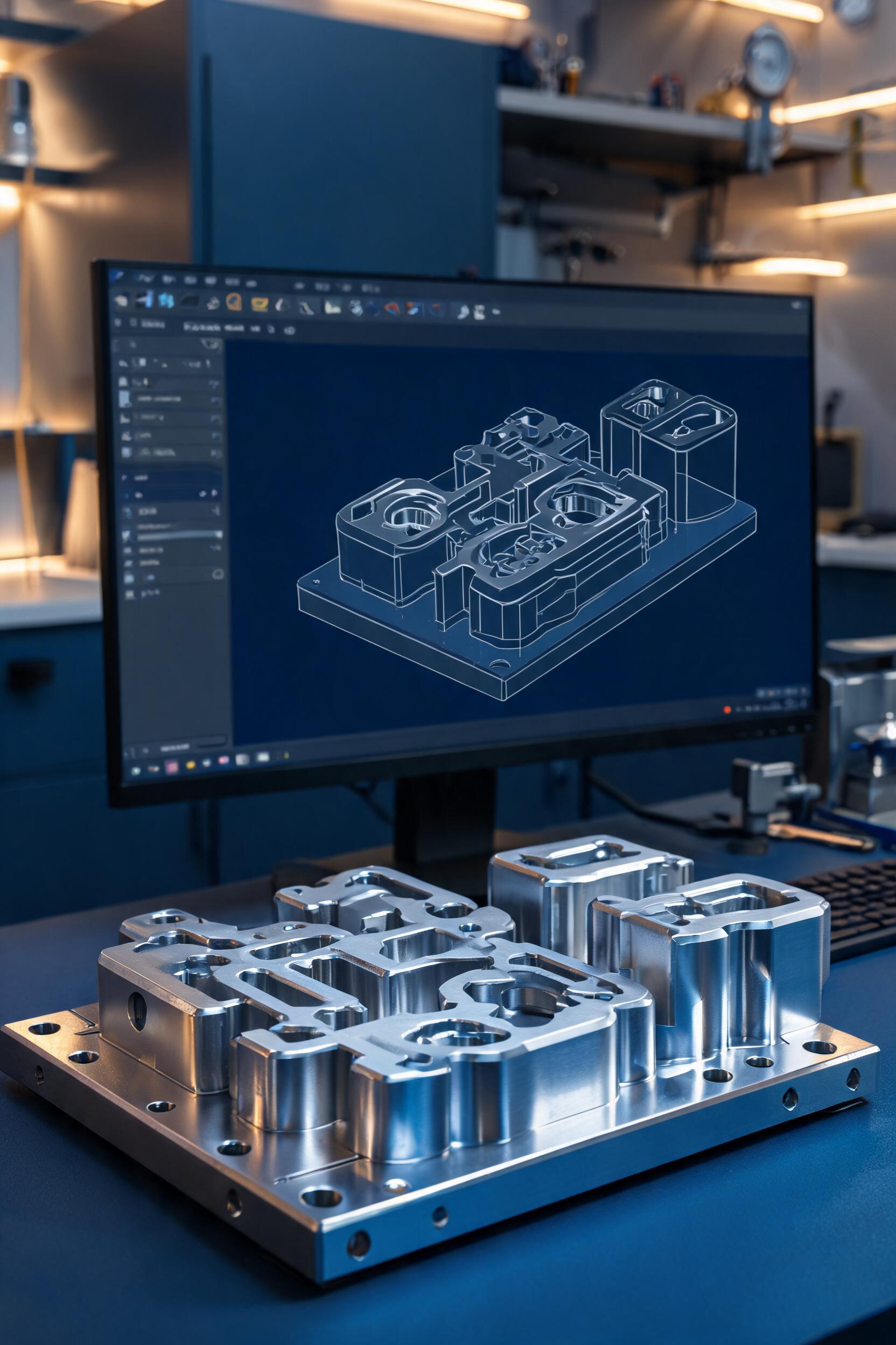
Custom rubber molds are the foundational manufacturing component for producing liquid silicone rubber (LSR), thermoplastic elastomer (TPE), and natural rubber parts with consistent dimensional accuracy, material performance, and surface finish across high-volume production runs. Unlike off-the-shelf mold solutions, 橡胶模具定制 (custom rubber mold) engineering is tailored to the unique geometric complexity, material compatibility, and production volume requirements of specific applications, ranging from medical device seals and automotive gaskets to consumer electronics keypads and aerospace O-rings. A 2023 industry survey by the Rubber Manufacturers Association found that 68% of precision rubber part defects trace back to suboptimal mold design or fabrication errors, highlighting the critical impact of end-to-end custom mold development workflows on final part quality. This guide breaks down the full custom rubber mold lifecycle, from design for manufacturability (DFM) validation to post-production quality control, with actionable parameters and testing protocols to mitigate common production risks.
Phase 1: Pre-Production Design and Material Matching for Custom Rubber Molds
The success of a custom rubber mold project is determined long before machining begins, with 70% of total production costs locked in during the design and material selection phase. This phase prioritizes alignment between part performance requirements, mold material properties, and manufacturing feasibility to avoid costly rework later in the process.
DFM Analysis for Rubber Molding Specifics
Rubber materials exhibit unique curing shrinkage, flow behavior, and demolding characteristics that require specialized DFM adjustments not applicable to plastic injection molds. Core DFM evaluation criteria for custom rubber molds include:
ParameterLSR MoldsHigh-Temperature Silicone MoldsNatural Rubber Molds
Recommended Draft Angle1.5–3° for vertical walls, 0.5° for textured surfaces2–4° for high-hardness (60+ Shore A) parts3–5° for parts with undercuts <5mm depth
Shrinkage Rate Allowance2.0–3.5% (varies with cross-link density and part thickness)2.5–4.0% (higher for filler-reinforced formulations)1.5–2.5% (lower for carbon-black reinforced compounds)
Maximum Undercut Size Without Slides2mm (for demoldable elastic undercuts)1.5mm (due to higher post-cure rigidity)3mm (for low-hardness <40 Shore A compounds)
Minimum Wall Thickness0.2mm (for microfluidic and medical device parts)0.5mm (for high-temperature industrial components)0.8mm (for structural natural rubber parts)
DFM analysis also includes gating and venting placement simulation: for LSR molds, a minimum of 0.03mm vent depth is required to prevent trapped air that causes voids, while natural rubber compression molds require 0.1mm vents to accommodate volatile release during curing. For parts with tight dimensional tolerances (±0.01mm for medical applications), DFM teams will simulate curing-induced warpage using finite element analysis (FEA) to adjust cavity dimensions pre-machining.
Mold Material Selection Based on Application Requirements
The choice of mold base and cavity material directly impacts mold lifespan, part surface finish, and production cost, with selections tailored to production volume and rubber material compatibility:
- P20 Pre-Hardened Steel: Ideal for low-to-medium volume runs (10,000–100,000 cycles) of general-purpose silicone and TPE parts. Hardness ranges from 28–32 HRC, with a maximum surface finish of Ra 0.2µm for transparent optical components. Not recommended for abrasive filler-reinforced rubber compounds, as it exhibits 2–3x faster wear than hardened tool steel.
- H13 Hot Work Tool Steel: The standard for high-volume custom rubber molds (100,000–1,000,000 cycles), particularly for high-temperature curing applications (180–220°C). H13 is heat-treated to 48–52 HRC, with excellent thermal fatigue resistance and compatibility with abrasive compounds such as glass-fiber filled LSR and carbon-black reinforced natural rubber. It can be polished to Ra 0.05µm for medical implant parts that require zero surface defects.
- Stainless Steel (420SS/316SS): Mandatory for molds used in medical and food-contact rubber part production, as it resists corrosion from repeated steam sterilization and acidic rubber additives. 420SS is hardened to 45–50 HRC for wear resistance, while 316SS is used for low-volume biocompatible parts due to its superior corrosion resistance, despite lower hardness (28–32 HRC).
- Aluminum 7075-T6: A cost-effective option for prototype and low-volume runs (<10,000 cycles) with lead times 40–50% shorter than steel molds. It is limited to low-temperature curing compounds (<150°C) and cannot support undercuts or complex slide mechanisms due to lower structural rigidity.
For molds intended for 1 million+ cycles, optional surface treatments such as titanium nitride (TiN) coating (2500 HV hardness) or diamond-like carbon (DLC) coating (3000 HV hardness) reduce wear by 60% and eliminate the need for frequent mold polishing.
Phase 2: Custom Rubber Mold Fabrication and Assembly Workflow
Once design and material selection are finalized, the fabrication process translates digital models into production-ready tooling, with tight tolerance control at every machining step to ensure cavity consistency and long-term performance.
Precision Machining and Cavity Finishing
The machining process for custom rubber molds follows a structured sequence to minimize dimensional deviation and internal stress:
- Rough Machining: High-speed CNC mills remove 90% of excess material from the mold base, leaving a 0.3–0.5mm stock allowance for finish machining. This step is performed at low cutting speeds to prevent heat-induced warpage of the steel blank, with post-machining stress relief annealing (600°C for 4 hours for H13 steel) to eliminate residual internal stress that could cause dimensional shift during production.
- Finish Machining: 5-axis CNC machining with ±0.005mm positioning accuracy cuts the final cavity geometry, followed by electrical discharge machining (EDM) for complex undercuts, micro-features, and internal corners that cannot be accessed by cutting tools. For micro-molds used in producing 0.1mm thick LSR microfluidic chips, wire EDM with 0.02mm diameter wire achieves corner radii as small as 0.01mm.
- Cavity Polishing: Polishing is performed sequentially from 180 grit to 1200 grit abrasive pads, followed by diamond paste polishing for high-gloss or optical parts. For medical molds, all polishing steps are performed in a cleanroom environment to prevent embedded contaminants that could transfer to rubber parts during production. Polished surfaces are inspected using a profilometer to confirm compliance with required surface finish specifications, with a maximum allowable deviation of ±0.02µm Ra for implantable part molds.
A critical quality check during machining is cavity dimensional verification: every critical feature is measured using a coordinate measuring machine (CMM) with ±0.001mm accuracy, with a minimum of 10 measurement points per cavity for multi-cavity molds. Multi-cavity molds must have a maximum cavity-to-cavity dimensional deviation of ±0.01mm to ensure consistent part quality across all production outputs.
Assembly, Gating, and Hot Runner System Integration
Mold assembly is a precision process that ensures proper alignment of cavity and core plates, gating systems, and temperature control components:
- Mold Alignment: The core and cavity plates are aligned using precision guide pins and bushings with a maximum allowable misalignment of 0.005mm. For high-precision molds, taper lock interlocks are added to prevent lateral shift during high-pressure injection, which can cause flash on part edges.
- Gating System Design: Gating is tailored to the rubber material and part geometry:
- *Cold Runner Systems*: Low-cost option for LSR and natural rubber, with gate diameters ranging from 0.2mm for micro-parts to 2mm for large gaskets. Cold runners generate 15–30% material waste per cycle, making them ideal for low-volume runs where material costs are minimal.
- *Hot Runner Systems*: Preferred for high-volume LSR production, with heated runner manifolds that maintain the LSR at 40–60°C (below curing temperature) before injection into the heated cavity. Hot runners reduce material waste to <2% and cut cycle times by 20–30%, but require precise temperature control (±1°C accuracy) to prevent premature curing in the runner system.
- Temperature Control Integration: For compression and transfer molds, cartridge heaters are embedded in the mold plates with thermocouple feedback to maintain uniform cavity temperature within ±2°C across the entire mold surface. Temperature non-uniformity of more than 5°C can cause uneven curing, leading to 30% lower part tensile strength and premature failure.
Post-assembly, the mold undergoes a dry cycle test: 50 consecutive open/close cycles under production pressure to verify that all slides, ejector pins, and gating components operate without binding. Ejector pin placement is adjusted to ensure even demolding force, preventing part deformation during ejection for low-hardness (30–40 Shore A) rubber components.
Phase 3: Mold Validation and In-Production Quality Control
Even perfectly fabricated molds require rigorous validation to confirm they meet part performance requirements before full-scale production, followed by ongoing quality control to maintain performance across the mold’s lifespan.
First Article Inspection (FAI) and Process Qualification
First article inspection is the critical final step before full production, validating both mold performance and part compliance with design specifications:
- Trial Run Production: A minimum of 100 sample parts are produced under standard production parameters (injection pressure 80–120 bar, curing temperature 180°C, curing time 30s/mm of part thickness) to simulate real operating conditions. For multi-cavity molds, 20 parts per cavity are collected to evaluate cavity-to-cavity consistency.
- Dimensional and Performance Testing: FAI includes:
- Dimensional verification of 100% of critical part features using CMM and optical measurement tools, with a 0% rejection rate required for features with tolerances tighter than ±0.05mm.
- Material performance testing: tensile strength (per ASTM D412), elongation at break, compression set (per ASTM D395), and hardness testing to confirm the curing process is optimized. For medical parts, biocompatibility testing (ISO 10993) is performed on first article parts to confirm no leachable contaminants from the mold surface.
- Defect analysis: Common defects such as flash, voids, short shots, and surface blemishes are traced back to mold issues: flash indicates insufficient clamping force or cavity misalignment, while voids point to inadequate venting or low injection pressure. A maximum allowable defect rate of 0.1% is required for FAI approval.
- Process Capability (Cp/Cpk) Testing: For high-volume production molds, a Cpk value of ≥1.33 is required, indicating that the process is statistically capable of producing parts within tolerance 99.99% of the time. Molds with Cpk <1.33 require design adjustments, such as gating modifications or cavity dimension tweaks, before full production approval.
Ongoing Mold Maintenance and Quality Monitoring
Custom rubber molds require regular preventive maintenance to extend lifespan and prevent quality degradation over production runs:
Maintenance TaskFrequencyAcceptance Criterion
Cavity surface cleaning and inspectionEvery 10,000 cyclesNo visible wear, scratches, or residue buildup; surface finish remains within ±0.05µm Ra of original specification
Guide pin/bushing lubrication and alignment checkEvery 25,000 cyclesMaximum misalignment <0.005mm; no binding during dry cycle testing
Ejector pin wear inspectionEvery 50,000 cyclesEjector pin length deviation <0.01mm; no burrs on pin tips
Full dimensional cavity verificationEvery 100,000 cyclesAll critical features within original tolerance range; wear depth <0.02mm on high-contact surfaces
Heater and thermocouple calibrationEvery 6 monthsTemperature uniformity across cavity ±2°C or better
For molds producing abrasive filler-reinforced rubber parts, inspection frequency is doubled, as filler particles can accelerate cavity wear by 3x compared to unfilled LSR. Any detected wear is addressed via diamond polishing for minor scratches, or cavity re-machining and plating for wear depth exceeding 0.02mm.
In addition to scheduled maintenance, in-production quality checks are performed every 4 hours during production runs, including dimensional sampling of 5 parts per cavity and visual inspection for flash or surface defects. Any deviation from specification triggers an immediate mold shutdown and inspection to prevent large batches of defective parts.
Conclusion
橡胶模具定制 (custom rubber mold) development is a precision-driven, multi-stage process that requires close alignment between design, engineering, and quality control teams to deliver consistent, high-performance results. By prioritizing DFM analysis tailored to rubber’s unique material properties, selecting mold materials matched to production volume and application requirements, maintaining ±0.005mm machining accuracy during fabrication, and implementing rigorous FAI and ongoing maintenance protocols, manufacturers can reduce mold rework rates by 80%, extend mold lifespan by 40%, and achieve final part defect rates below 0.05% for high-volume production runs. As demand for precision rubber components grows in the medical, automotive, and aerospace sectors, adherence to these structured custom mold development workflows will remain the most critical factor in delivering parts that meet strict regulatory and performance requirements over the full product lifecycle. For organizations looking to optimize custom mold projects, partnering with mold fabricators that specialize in rubber-specific design and have in-house material testing capabilities can reduce project lead times by 30% and lower total production costs by 25% compared to general-purpose mold providers.